Faber STILO Wall Mount Canopy Rangehood Installation Instructions Manual Download Page 6

Version 05/08 - Page 6


DUCTLESS 

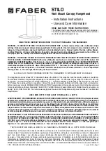
INSTALLATION  DIMENSIONS

upper 

chimney 

cover

ductless 

lower 

chimney 

cover

canopy

x = distance from hood to cooktop

(varies depending on installation)

min - 24”, suggested max - 30”

cabinet base

10" min

16 

1/8”

 max

21 

1/4"

3/8"

36”

19 

9/32"

x

also consult cooktop

manufacturer's recommendation


(not vented to the outside)

FIGURE 4B DUCTLESS INSTALLATIONS

The Stilo chimneys are adjustable and designed 

to meet varying ceiling heights as indicated 

in 

FIGURE  4B

.    For  ductless  installations, 

the  chimneys  can  be  adjusted  for  ceilings 

between 7' 9 5/8" and 8' 9 3/4" depending on 

the distance between the bottom of the hood 

and the cooktop

 (distance x)

.

For shorter ceilings, have the chimney cover(s) 

cut at a sheet metal shop.    For higher ceiling 

installations, the 

High Ceiling Chimney Kit


includes a new 40” upper chimney which would 

replace the 16 1/8” upper chimney that came 

with the hood.

min & max ceiling height examples

x = 30"

min

8' 

3 5/8"

max

8' 

9 3/4"

x = 28"

min

8' 

1 5/8"

max

8' 

7 3/4"

x = 26"

min

7' 

11 5/8"

max

8' 

5 3/4"

x = 24"

min

7' 

9 5/8"

max

8' 

3 3/4"

Summary of Contents for STILO Wall Mount Canopy Rangehood

Page 1: ...Title 24 HUD Part 280 Four wire power supply must be used and the appliance wiring must be revised See Electrical Requirements LISEZ BIEN CETTE FICHE AVANT D INSTALLER LA HOTTE AVERTISSEMENT POURMINI...

Page 2: ...ral Ventilating Use Only Do Not Use To Exhaust Hazardous or Explosive Materials and Vapors WARNING TO REDUCE THE RISK OF FIRE ELECTRI CAL SHOCK OR INJURY TO PERSONS OBSERVE THE FOLLOWING InstallationW...

Page 3: ...as perforer un autre fil lectrique Une ventilateur vacuation ext rieure doit tre raccord e l ext rieur AVERTISSEMENT Le syst me d vacuation DOIT sortir l ext rieur N VACUEZ PAS le conduit soit dans un...

Page 4: ...RTS NEEDED FOR INSTALLATION 2 Conduit Connectors Power Supply Cable 1 Wall or Roof Cap All Metal Ductwork OPTIONAL ACCESSORIES AVAILABLE Backsplash Choose either 24 or 30 high mounts to the wall benea...

Page 5: ...eiling installations the High Ceiling Chimney Kit includesanew40 upperchimneywhichwould replace the 16 1 8 upper chimney that came with the hood upper chimney cover lower chimney cover canopy x distan...

Page 6: ...eet varying ceiling heights as indicated in FIGURE 4B For ductless installations the chimneys can be adjusted for ceilings between 7 9 5 8 and 8 9 3 4 depending on the distance between the bottom of t...

Page 7: ...n FIGURE 5A or 5B and install the MOUNTING SCREWS into the wall leaving about 1 4 gap between the wall and the head of the screw 8 For ducted installations determine and make all necessary cuts in the...

Page 8: ...e grounding lead to the green screw provided Attach the White lead of the power supply to the White lead of the rangehood with a twist on type wire con nector Attach the Black lead of the power supply...

Page 9: ...should not be used to clean finished surfaces Replacing the Lamps Before attempting to replace the lamps make sure that the light switch is turned off Remove the 2 screws as indicated in FIGURE 14 th...

Page 10: ...umbing 2 Service calls to repair or replace range hood light bulbs fuses or filters Those consumable parts are excluded from warranty coverage 3 Repairs when your range hood is used for other than nor...

Page 11: ...toit Conduit en m tal ACCESSOIRES POUR L INSTALLATION Dosseret 30 po X 24 po haute part 6098835 Acier Inoxydable 30 po X 30 po haute part 620000095 Acier Inoxydable 36 po X 24 po haute part 6098815 A...

Page 12: ...diff rentes hauteurs de plafond entre 7 pi 4 3 4 po et 8 pi 9 3 4 po regardez la distance entre la hotte et la table de cuisson X en FIGURE 4A Celas accomplitenutilisantplus ou moins du couvercle de l...

Page 13: ...t r glable pour diff rentes hauteurs de plafond entre 7 pi 9 5 8 po et 8 pi 9 3 4 po regardez la distance entre la hotte et la table de cuisson X en FIGURE 4B Cela s accomplit en utilisant plus ou moi...

Page 14: ...r et la t te de la vis 8 Pour les installations avec conduit d terminer et faire toutes les coupes n cessaires dans le mur pour les conduits Installer les conduits avant la hotte 9 D terminerl emplace...

Page 15: ...t jaune et vert sous la vis de mise la terre verte Replacer le couvercle du compartiment de c blage 2 Installer la CHEMIN E SUP RIEURE C de la FIGURE 10 Elargir l g rement les deux bords lat riaux de...

Page 16: ...ansunesolutiond eauchaudeetded tergent ou mettre au lave vaisselle Utiliser un nettoyant pour l acier inoxydable sur les hottes en acier inoxydable Ne pas utiliser de produits abrasifs ou de r curants...

Page 17: ...e maison ou pour corriger votre c blage ou votre syst me de plomberie 2 Les appels de service pour remplacer ou r parer les ampoules les fusibles ou les filtres de votre hotte de cuisini re 3 Les r pa...

Reviews: