33
4
SETTINGS
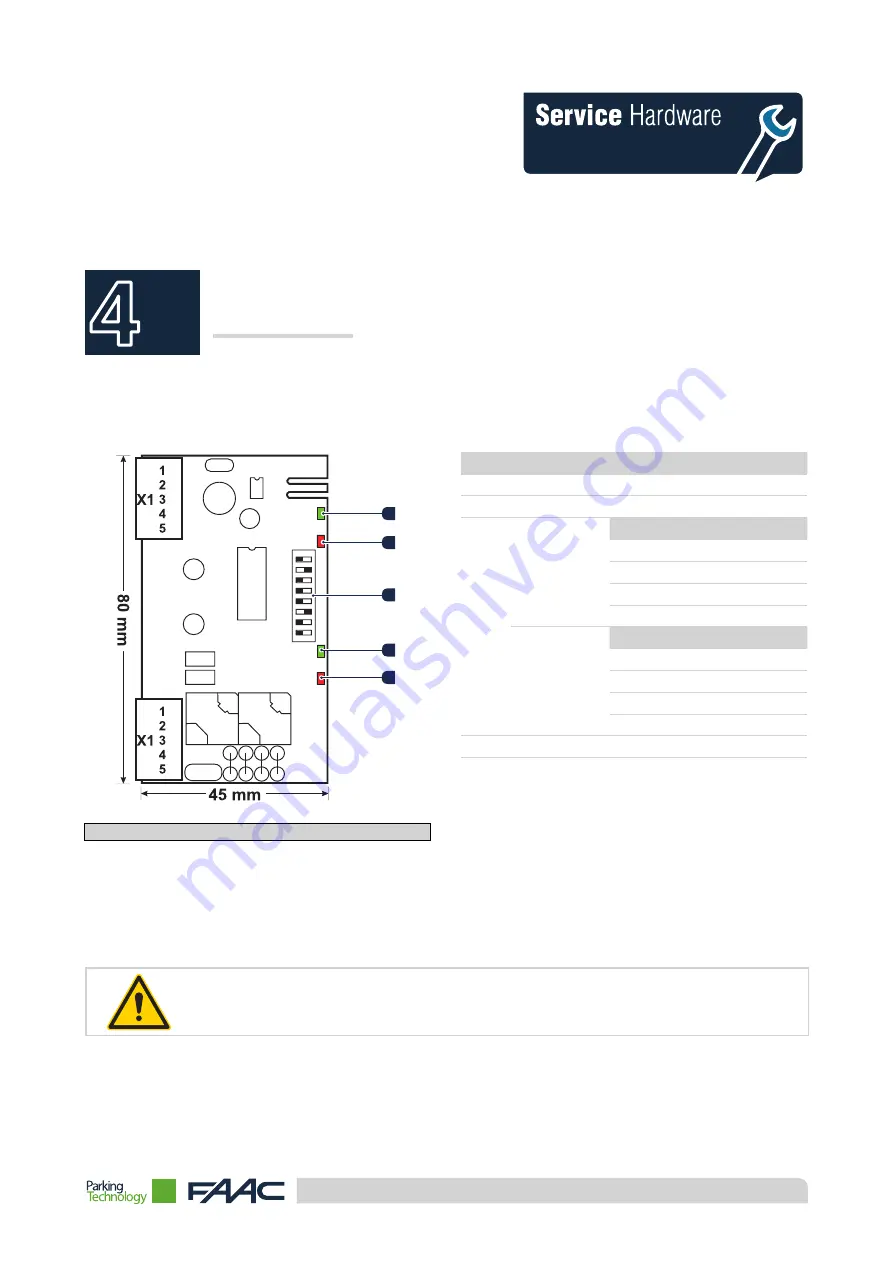
4.1 DETECTOR DP2
The device is inserted into the interface board and retains the vehicles that transit on the lane.
7
6
5
4
3
1
2
3
4
5
2
1
8
ON
Figure 19 -
Two-channel detector DP2
Pos. Description
1
Channel 2 - Green LED (Channel Status)
2
Channel 2 - Red LED (Vehicle on Loop)
3
Channel 2
Pin
Description
8
Frequency
7
Retaining time
6
Sensitivity B
5
Sensitivity A
Channel 1
Pin
Description
4
Frequency
3
Retaining time
2
Sensitivity B
1
Sensitivity A
4
Channel 1 - Green LED (Channel Status)
5
Channel 1 - Red LED (Vehicle on Loop)
4.1.1. Setting of detector DP2
The detector is set via the 8 dip switches (see point "3" table above) on the side of the electronic board.
The variation of position of each of these allows the operating characteristics of this component to be changed. The various
steps that follow describe all the possible configurations.
The following tables indicate the default setting with the "♦" symbol.
Ver. 1.0 - 21st Nov. 2014 - ENG
Summary of Contents for PARQUBE LE
Page 1: ...PARQUBE LE Installation Ver 1 0 21st Nov 2014 ENG ...
Page 2: ......
Page 3: ...3 This page has been left blank intentionally Ver 1 0 21st Nov 2014 ENG ...
Page 6: ...6 This page has been left blank intentionally Ver 1 0 21st Nov 2014 ENG ...
Page 10: ...10 This page has been left blank intentionally Ver 1 0 21st Nov 2014 ENG ...
Page 40: ...HUB Parking Technology a Business Unit of the FAAC Group www hubparking com ...


