


T
T
ROUBLESHOOTING
ROUBLESHOOTING
T
T
IPS
IPS
F
AULT
L
IGHT
C
OUNT
:
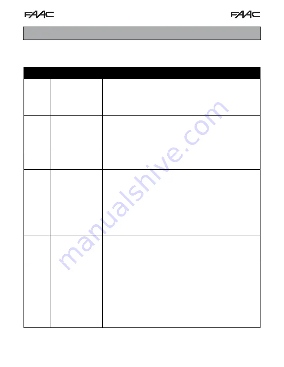
The gate operator control board has a Fault Light to help determine fault shutdowns. If the operator is not functioning properly,
remove the cover and check the Fault Light for the operator Fault Status. Use the following chart to determine the Fault:
Number of
Blinks
Fault Description
2
Sensitivity/Current
Overload:
Second Time
3
Run Time Fault
4
Sensor Fault/Failure
5
PCB Overheat Fault
6
Master Slave Fault
1
Sensitivity/Current
Overload:
First Time
Cause & Action
Operator detected an unexpected current overload while moving. Usually caused
by the gate hitting an obstruction or tripping the sensitivity. This will put the
operator in a Soft Shutdown.
1. Make sure the sensitivity settings are set correctly. Too light of a setting will
cause the gate to stop and fault.
2. Make sure there are no external obstructions that are causing the gate to stop
and shutdown.
Operator detected an unexpected current overload while moving a second time.
Usually caused by the gate hitting an obstruction or tripping the sensitivity. This will
put the operator in a Hard Shutdown.
1. Make sure the sensitivity settings are set correctly. Too light of a setting will
cause the gate to stop and fault.
2. Make sure there are no external obstructions that are causing the gate to stop
and shutdown.
Operator has run longer than normal. Usually caused by a bad limit or wiring fault
1. Check the limit for normal operation.
2. Make sure the limit wires Connections are tight .
Motor Sensors have failed. Usually caused by a bad sensor or loose sensor wire.
1. Make sure the sensor wires are tight and well connected to the blue connector.
While the operator is stopped, wiggle the Limit/Sensor connector. If the limit or
sensor wires blink on and off, there is a loose connection.
2. Start the operator, watch Sensor 1 and Sensor 2 at startup. They should both
blink before turning solid. If only one blinks, then the non-blinking sensor is not
being seen.
3. Remove the motor from the gearbox. Both sensor lights should be on. Pass a
flat screw driver between Sensor 1 and Sensor 2 on the motor plate. The
Sensor LED on the control board should turn off and on as the screw driver
passed through it.
4. Make sure the sensor cup on the gearbox shaft is tight. A loose sensor cup will
slip and cause the sensors to miss counts.
Operator PCB has become too hot and caused a fault.
1. Make sure the control board heat sink is secured to the side of the controller box
to help dissipate excess heat.
2. Determine if the operator has run excessively to cause an overheating problem.
3. Possibly a defective heat sensor on the control board. Have board repaired.
Master Slave communication has failed. Usually caused by a loose Master Slave
wire or connector. A very strong lightning strike can sometimes cause damage to
the master slave circuit on the control board.
1. Make sure the master slave wires are connected correctly and tight.
2. Unplug the master slave wire and set both operators as Masters. Test each
operator independently to make sure there are no other problems or faults. After
determining each operator runs by itself, reset the master slave settings and
connect the master slave wire. If the problem continues, recheck wire and wire
connections.
3. Run a new CAT5 wire on top of the driveway to test the master slave
communication. This will determine if the underground wire is good or bad.
4. Possible damage to the control board master slave components. Have boards
repaired.
FSL700 Slide Gate Operator
29


