background image


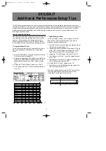
•  The magnetic loops must be positioned as shown in fig. 5: 

only if positioned in this configuration, the loops are able to 
manage the vehicle count in a correct way and to control 
the  re-closure  of  the  barrier  exclusively  after  the  vehicle 
has transited. However the dimensions can be adapted to 
the  lane  width  and  to the  type  of  vehicles  to  detect: fig.5 
shows the loops to be used in the event of a lane width of 
2.5 m for cars and vans.  


•  The Token Acceptor and the Barrier must be installed on 

an  island  lifted  by  approx. 

15  cm

.  with  respect  to  the 

street  surface  in  order  to  protect  them  against  impacts 
during  vehicle  movement.  If  this  is  not  possible,  install 
suitable  protective  structures  around  the  base  of  both 
housings.  


.


4.3.     REALIZING THE MAGNETIC LOOPS


The  magnetic  loops  can  be  realised  in  two  different  ways: 
laying  the  cable  directly  in  a  chase  made  in  the  existing 
pavement or, this is the best solution, realising a cable duct in 
PVC before the pavement is made.


In  both  cases, the  cable must  be  laid  not  over  5  cm from the 
surface and not less than 15 cm from covers or other metallic 
objects.


In case of a cable duct, you can use a normal single-pole cable 
with 1.5 mm² section. On the contrary, the cable directly laid in 
the  chase  must  have  the  same  section  but  with  double 
insulation (for the realisation of the chase, see chapter 4.4.1.). 
 
The  loop must be  realised  with  a  single  cable  without making 
any joints. Both ends of the cable must be twisted each other 
(

at  least  20  times  per meter

)  for the  whole  section  from the 

loop to the Detector terminal board.


The number of windings of the loops is 4.


POSITIONING LAYOUT OF ENTRY/EXIT LANE DEVICES 

Foundation plate for Token 
Acceptor GRS-02 

Foundation plate for Barrier 620 rapid 
(RH version) 

Sense of direction 

Presence loop 

Transit loop 

Loop made of 4 
windings 

ENGLISH 

ENGLISH 

Summary of Contents for F0254

Page 1: ...forms to the essential safety requirements of the following EEC directives 73 23 EEC and following modification 93 68 EEC 89 336 EEC and following modification 92 31 EEC and 93 68 EEC Additional notes this product underwent tests in a typical homogeneous configuration all products by FAAC S p A Bologna 2nd January 2009 The Managing Director A Marcellan 1 ...

Page 2: ... gas or inflammable fumes is a serious danger to safety 8 FAAC is not responsible for failure to observe Good Technique in the installation of the product 9 Before attempting any job on the system cut out electrical power 10 Make sure that a differential switch with threshold of 0 03A is fitted upstream of the system 11 Make sure that the earthing system is perfectly realised and connect the yello...

Page 3: ...strian configuration the token insertion slot must be always open in this case the shutter must be physically removed In the vehicle configuration by interfacing a Single or a Two Channel Detector you can enable the token insertion only in the presence of a vehicle in this case pedestrians are not allowed to use the lane Tab 1 Technical Specifications GRS 02 Token Acceptor 2 DIMENSIONS fig 2 3 POW...

Page 4: ...ll if possible adequate means of protections against accidental impact Check that an efficient earth socket is available for connecting the housing of the Token Acceptor 4 2 POSITIONING THE COMPONENTS 4 2 1 PEDESTRIAN ACCESS Before placing the foundation plate of the GRS 02 Token Acceptor make sure the following conditions are observed The Token Acceptor must be installed in such a way not to expo...

Page 5: ... laying the cable directly in a chase made in the existing pavement or this is the best solution realising a cable duct in PVC before the pavement is made In both cases the cable must be laid not over 5 cm from the surface and not less than 15 cm from covers or other metallic objects In case of a cable duct you can use a normal single pole cable with 1 5 mm section On the contrary the cable direct...

Page 6: ...inth as shown in fig 10 and wall the foundation plate supplying one or more sheaths for routing electrical cables Using a spirit level check if the plate is perfectly level Wait for the cement to set fig 10 3 Prepare the electric cables for the connection as indicated in Chapter 3 1 3 2 or 3 3 according to the type of use For easy connection let the cables come out of the foundation plate hole for...

Page 7: ...y can be set on two levels according to the position of the loop connector Frequency depends furthermore on the loop shape on the number of windings and on the cable total length N B For any further explanations on the operation of the detector FG1 please refer to the specific instructions of the product 5 3 VEHICLE ACCESS IN LOGIC P In the configuration for the management of a lane in logic P you...

Page 8: ...esence OFF OFF LOW ON OFF MEDIUM LOW OFF ON MEDIUM HIGH ON ON HIGH SW3 SW4 LOOP 2 SENSITIVITY transit OFF OFF LOW ON OFF MEDIUM LOW OFF ON MEDIUM HIGH ON ON HIGH Frequency selection The detector operating frequency can be set on two levels using the dip SW5 The detector automatically changes the frequencies of both loops Frequency depends furthermore on the loop shape on the number of windings and...

Page 9: ...HE CONNECTION OF PHOTOCELLS AND SAFETY DEVICES REFER TO PARAGRAPH 4 1 BEAM BREAKTHROUGH BARRIER 620 640 SET IN LOGIC P OPEN CLOSED COMMANDS OPEN BARRIER CLOSED BARRIER LOOP 2 Safety stop command logic p on 624 BLD OPEN CLOSED COMMON CONTACT BARRIER PHOTOCELL MICROSWITCH ON GRS 02 ON N O CONTACT RELAY ENGLISH ...

Page 10: ...IC A OPEN CLOSED COMMANDS OPEN BARRIER OPEN COMMON CONTACT Safety stop command logic A on 624 BLD BARRIER PHOTOCELL MICROSWITCH ON GRS 02 ON N O CONTACT LOOP 2 MOTOR FAN MOTOR THRUST CAPACITOR BEAM BREAKTHROUGH FOR THE CONNECTION OF PHOTOCELLS AND SAFETY DEVICES REFER TO PARAGRAPH 4 1 RELAY ENGLISH ...

Reviews: