background image

5.2 

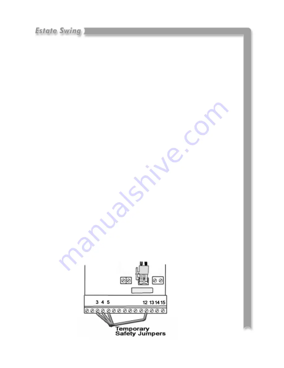
Installing temporary safety jumpers 

For your opener to function properly a few connections must be made prior to 
the learning process. Accessories should 

NOT

 be installed until after the learn-

ing process is completed. 
 
 
Using the provided jumper wire, connect the normally closed safety terminals 
(terminals 3, 4, and 5) to one of the negative terminals (terminals 12, 13, 14, or 
15). Do this by cutting and stripping the wire into 4 sections and twisting the 3 
from the safety terminals together with the fourth which will lead to the com-
mon terminal. The connection can be secured with electrical tape or a wire nut.  
 

This allows one terminal to be freed for a safety device but the others to be able 
to still be jumped out so the operator will run. 

 
We recommend that these jumpers are later replaced with safety devices after 
learning is complete. If you choose not to replace the jumpers with safety de-
vices you 

MUST 

keep the jumpers in.  


Your connections can be checked using the diagnostics mode

. Press 

P2 once

C, D, and E should be lit. After checking press P2 again to exit the diagnostics 
mode. To learn more about diagnostics see section 7. 

Summary of Contents for Estate Swing E-SC 1102 Series

Page 1: ...Instruction Manual for the Manufactured by E SC 1102 Series...

Page 2: ...allation must conform to Standards EN 12453 and EN 12445 The safety level of the automated system must be C D 10 Before attempting any job on the system cut out electrical power and disconnect the bat...

Page 3: ...the battery The SLAVE equipment is controlled by the MASTER equipment to which all accessories and pulse gen erators are connected The MASTER card can be programmed and is used to set the following f...

Page 4: ...ing 2 Control Board Layout 2 1 IMPORTANT Charging Battery Prior to Use 2 2 3 Basic Installation 3 IMPORTANT Setback Clearance 3 1 Installation of Mounting Hardware and Arm 3 2 3 Mounting Control Box 4...

Page 5: ...ting 7 Simple Diagnostics 7 1 Trouble Shooting 7 2 5 Logic Summaries and Flow Charts 7 6 7 Accessories 8 Accessory Terminals 8 1 2 Photocell Safety Device Guide 8 3 4 Installing Accessories 8 5 Table...

Page 6: ...3 CANNOT BE MODIFIED Use frequency cycles hour 5 Consecutive cycles on charged battery Max 15 Battery recharge time 10 min for each full cycle Operating ambient temperature 4 to 131 Deg F Operator wei...

Page 7: ...ion during entire travel Make sure the hinges are in good condition Ball bearing hinges are ideal for gates weighing over 200 lbs or over 10 in length Make sure the gate is plumb and level The fence p...

Page 8: ...ount Brackets E Transmitter F Receiver G Post Mounting nuts Manual Release Key H Transformer A Control Box B Operator Arm C Gate Mount Bracket D Post Mount Brackets G Post Mounting nuts Manual Release...

Page 9: ...erator Length is determined by distance between transformer power supply and the control box 8 5 16 Redheads Lag Screws and shields or other anchoring system will be needed to fasten the column bracke...

Page 10: ...safety cables push buttons receivers photocells etc To avoid any electrical noise use separate sheaths or a shielded cable with earthed shield Layout of Master Control Board Layout of Slave Control Bo...

Page 11: ...ery into the control board fig 1 For charg ing purposes it is not necessary to hook the receiver to the battery or control board 2 Insert the wires from the supplied AC transformer into terminal J2 of...

Page 12: ...f the master must connect with the left side of the slave fig 3 NEVER CONNECT POWER FROM ANY SOURCE DIRECTLY TO THE SLAVE BOARD The slave board may ONLY be connected to the Master control board Let th...

Page 13: ...l leverage during opening and closing cycles 3 1 The purpose of this page is to clarify and show examples of possible setbacks Install the brackets according to the installation directions following t...

Page 14: ...amples of industrial door stops 2 Position the column bracket to the dimensions from the previous page In most installations the gate is already hung so the distance between A and B is going to dictat...

Page 15: ...carry the gate an inch further by just turning the base gears of the operator 5 Manually release the opener arms Do this by removing the black cap o the top inserting the release key and turning it un...

Page 16: ...and attach the control box to the post 4 There are three separate knockouts on the bottom of the control box Find a water tight connector at your local hardware store that will fit one of the knockout...

Page 17: ...erminal strip at the bottom of the control board is easily removed for wiring Simply pull straight down on the terminal strip to remove it from the board It will slide right off Slide it back on when...

Page 18: ...ty terminals together with the fourth which will lead to the com mon terminal The connection can be secured with electrical tape or a wire nut This allows one terminal to be freed for a safety device...

Page 19: ...6 MUST connect with the RIGHT side of J2 on the Slave board Terminal 15 MUST connect with the LEFT side of J2 on the Slave board J3 Actuator Connections This terminal is used to connect the operator a...

Page 20: ...e Swing board Setting the Dip Switches 1 Set the dip switches on the receiver by switch ing them in the up down or center position Record this dip switch combination 2 Slide off the battery cover of t...

Page 21: ...Es tate Swing control board 3 Before plugging in your transformer plug the battery into the control board The clear plastic clip gets clipped into J4 with the clip side on the left The other side of t...

Page 22: ...ing full open By selecting Logic EP 4 all pause times will be void and the gate will remain open until an opening devices is triggered C Switches between the amount of time the gate waits before begin...

Page 23: ...s an increased amount of motion stop points 4 EP Stepped Semi automatic is designed to function similar to a garage door opener Turns off the auto close setting B Pause Times 1 5 Seconds 2 10 Seconds...

Page 24: ...6 times to light A E simultaneously While the 5 LEDs are lit steadily hold down P2 for about 3 seconds The operator will start the maneuver process Using P2 Briefly press the button once for each of...

Page 25: ...sing open stops 4 alt Press P2 to stop the openers opening motion and reverse the motion of the gate 3 Press P2 to teach leaf 2 opening decelera tion starting point Without open stops press P2 6 4 5 P...

Page 26: ...of arm Leaf 1 will begin closing 7 Press P2 to teach leaf 1 closing decelera tion starting point 8 Let the leaf 1 make contact with the full closed stop point or full closing point of arm Press P1 to...

Page 27: ...active for 5 minutes and then the board returns to all LEDs OFF WARNING When you access the input status function all acces sories are powered even with the gate idle P1 is active and can be used to...

Page 28: ...to the right Reverse the polarity for Push To Open Operation Check the fuse to be sure the fuse is not blown It can be tested visually or with a volt meter by checking for continuity between the two...

Page 29: ...te stops mid cycle Check the force setting D variable 4 is the highest Try moving the force to high Check the speed setting E variable If the gate is heavy and moves too quickly sometimes the jerk of...

Page 30: ...ual openers CDE and 1 should be on The rest off If 1 is off then the slave is not communicating with the master check your connection to the slave and the polarity of the connection Section 9 If using...

Page 31: ...to e mail digital photos to the technician This is done in your best interest to save unnecessary shipping expenses and time lost Many times we can come up with solutions to issues by seeing pictures...

Page 32: ...before re closing Re closes the leaf No effect Closes after 5 sec onds Closing Re opens the leaf No effect Reverses direction of motion Opening Re closes the leaf Reverses direction of motion No effec...

Page 33: ...ect Reverses direction of motion Opening Stops operation Reverses direction of motion No effect Stopped in mid cycle Restarts motion in opposite direction the gate was previously moving before stopped...

Page 34: ...g and or closing pulse for only the gate leaf controlled by the master control board 3 Stop Command This is a normally closed terminal where by any device i e push button which by opening a contact ha...

Page 35: ...connecting the master and slave board This will cause permanent damage to both boards and will void the war ranty Caution 7 8 Positive 7 8 24 Voltage Positive 24V for powering accessories that are run...

Page 36: ...act and crushing Closing Safety Devices They operate only during the gate closing movement and therefore are suitable for pro tecting the closing zone against the risk of impact Opening Closing Safety...

Page 37: ...8 4...

Page 38: ...ener to be active this cir cuit must be closed When a device opens this circuit it stops the motion of the gate operator This circuit is the main circuit for safety devices i e photo eyes safety loops...

Reviews: