8
LH
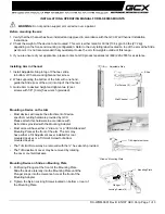
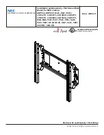
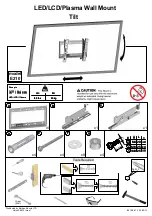
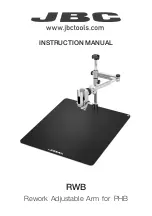
Fig. 4
RH
4.3.
Installation sequence
The DOMOLINK operator is available in 2 versions, designed for
installation according to leaf opening direction:
RIGHT
DOMOLINK
for right side installation (Fig. 4 - RH)
LEFT
DOMOLINK
for left side installation (Fig. 4 - LH)
4.2.
Installation dimensions
Establish the installation position of the operator by referring to
Fig. 3 and Table 2.
4.
INSTALLATION
4.1.
Preliminary checks
To ensure safety and an efficiently operating automated system,
make sure the following conditions are observed:
•
The enclosures of the control boards (see relevant
instructions) should be installed at a distance from the
operators not requiring the motor cable to be extended.
•The structure of the gate must be suitable for being
automated. In particular, check that the structure is
sufficiently strong and rigid, and that its dimensions and
weight conform to those indicated in the technical
specifications.
•Make sure that the leaves move uniformly and correctly,
without any irregular friction during their entire travel.
•Make sure that the hinges are in good condition.
•Check if the mechanical stops of the limit-switches are
fitted.
•Remove any locks and lock bolts.
We advise you to have any metalwork carried out before the
automated system is installed.
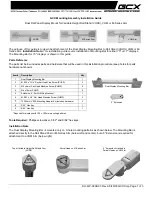
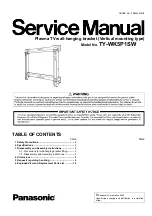
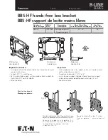
To select the dimensions, we advise you to measure dimension
D first and then position the rear fitting, using dimension B
among those indicated in Table 2.
Note:
Carefully check that the distance between the leaf
hinge and any obstacles (wall, fencing, etc.) is greater
than or equal to
min dimension
I
(Fig. 3) referring to the
selected opening angle, so that it does not interfere
with the opening movement of the operator.
Fig. 3
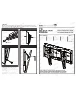
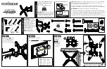
•
Dimensions in mm
Dimension D Dimension B
Angle
a
Dimension
I
min.
from to
from
to
30
160
100
160
90°
O
400
160
200
100
110
30
80
160
200
110°
O
500
30
50
180
200
120°
O
560
Tab. 2 -
Installation dimensions
•
Dimensions in mm
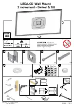
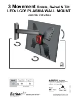
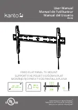
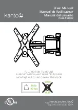
Fig. 5
4.3.1 Installing the rear fitting
Secure the rear fitting to the pillar by welding or using suitable
expansion plugs (Fig. 5), observing the dimension as shown in
Fig. 3 and Table 2 and checking if the fitting is perfectly
horizontal.
Ü
The rear fitting must never be cut and must face
downwards.