background image

5

4.

Installation

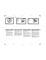
4.2   Installation of leaf supporting foundation box (fig.3)

4.1   Preliminary Checks

Proceed as instructed below:

To ensure trouble-free operation, make sure
that the gate (whether existing or yet to be
installed) are within following specifications:

–  max. weight of single leaf 800 Kg
–  max. length of single gate leaf 4 m (see 

table 1)

–  strong and rigid leaf frame
–  smooth gate movement
–  min. clearance between bottom edge of 

gate and ground as in fig. 6/a (where ‘s’ =
thickness of guide bracket)

–  mechanical travel stops.

If any welding or brazing has to be done on
the gate, do this before installing the
automation system.

a)

Existing gate with fixed hinges

–  Remove the gate.
–  Remove the bottom hinge.
If the gate cannot be removed, place 
blocks under its bottom edge to support it.

b)

Existing gate with adjustable hinges

–  Remove the bottom hinge.
–  Slacken off the top hinge.
–  Swing the leaf around the axis of the 

top hinge (fig. 4).

c)

New gate to be installed

–  Fit just the top hinge. If possible use an 

adjustable hinge.

Fig. 6/a

Fig. 3

Fig. 4

Summary of Contents for 760

Page 1: ...lug the equipment from the electrical supply network either by removing the plug or by turning off the system s main switch An isolation switch should be provided for the installation according to by...

Page 2: ...x Manual release 418137 1 x Electronic control unit 450 MPS 790902 1 x Control box container 720118 1 x 418mhz receiver IRM418 1 x MINIDEC decoder IMINIDECSL 1 x 418 mhz transmitter ITI418 1 x FAAC L...

Page 3: ...chnical Specifications 1 Bleed screw 2 By pass valves 3 Release device 4 Release lock optional accessory 5 Oil filler plug 6 Mechanical travel stop adjusting screw 7 Deceleration ramp adjusting screw...

Page 4: ...e opening closing stationary internal TA TC F x 100 TA TC TP TI TA opening time TC closing time TP stationary time TI length of interval between one complete cycle and the next duty cycle Time h 3 1 M...

Page 5: ...bottom edge of gate and ground as in fig 6 a where s thickness of guide bracket mechanical travel stops If any welding or brazing has to be done on the gate do this before installing the automation s...

Page 6: ...of quick setting concrete at the bottom of the hole to avoid subsidence in future 2 Insert the base box in the hole fig 6 a b The centre of the pinion must be perfectly aligned with the leaf s axis of...

Page 7: ...water drain fig 8 4 Fix the box with concrete N B Wait for the concrete to set before starting this work 1 Prepare the gate guide bracket as follows Use a U profile of the dimensions given in fig 9 As...

Page 8: ...Seal the U profile on the post side with a plate as shown in fig 13a b 2 Grease the pinion 3 Fit the guide bracket over the pinion so that the tooth with the punch mark engages in the bushing notch a...

Page 9: ...tallation To determine the precise angle a measure the length of line L fig 17 and position the gate at the mid point of the line 4 Fit the operator inside the box and engage the rack ram with the pin...

Page 10: ...the outer edge of the gate Use a linear dynamometer to ensure that force at the outer edge of the gate is measured accurately Turn the by pass valve screws as shown in fig 19 to set the anti crushing...

Page 11: ...ed position limit stop 8 Slacken off the lock nut from the open travel stop adjusting screw fig 20 a 9 Slacken off the open travel stop adjusting screw fig 21 until the leaf starts moving 10 Screw in...

Page 12: ...oundation box move the leaf manually to a distance D from its fully closed position D L x 0 76 fig 23 where L leaf length See section 5 2 for details on how to set the internal closed position travel...

Page 13: ...can only be removed when in vertical position Checking the oil level The oil level must be kept just below the filler plug hole fig 27 For low to medium duty cycles you need only change the level once...

Page 14: ...the operator reaches the end of the opening cycle 5 Give a closing signal to the gate 6 While the gate is closing remove the access cover and slacken off the closing bleed screw ref D fig 20 a b as sh...

Page 15: ...chnical or commercial reasons at any time and without revising the present publication Your Authorised FAAC Dealer Simply the world s best welcome And that s a FAACT FAAC UK Ltd Old Brick Kiln Ramsdel...

Reviews: