


5
Fig.19
Fig.20
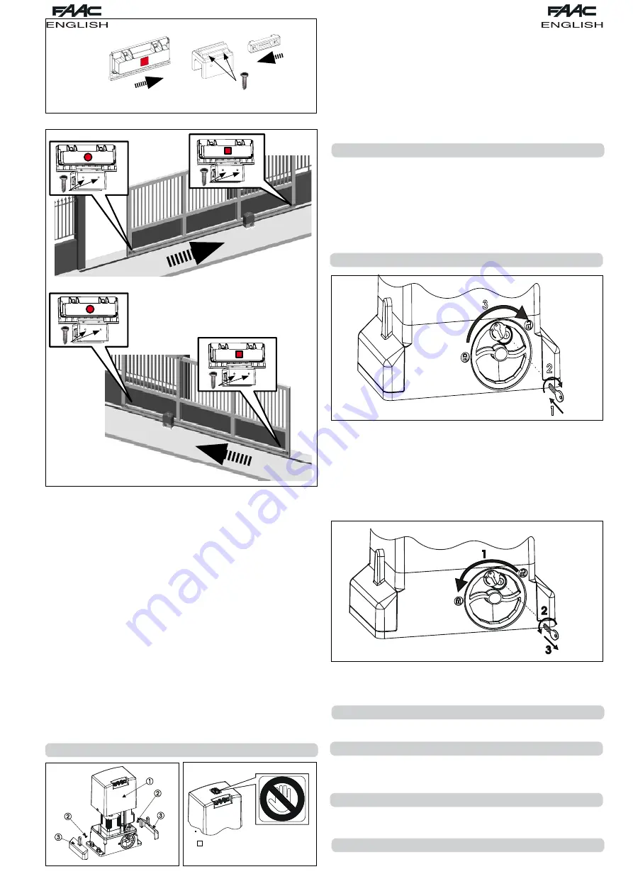
1) Assemble the two magnets as indicated in figure 18.
2) Prepare the operator for manual operation, as indicated in
paragraph 8, then power up the system.
3) Manually move the gate into the open position, leaving 40 mm
from the travel limit mechanical stop
4) Slide the magnet closest to the operator along the rack, in the
direction of the motor. As soon as the LED for the limit switch on
the board switches off, move the magnet forward by another
10 mm and fix it with the appropriate screws.
5) Proceed in a similar way for the other magnet.
6) Move the gate approximately half way through its run and
re-lock the system (see paragraph 9).
Important :
Before sending an impulse, ensure that the gate cannot
move manually.
7) Perform a complete gate cycle to check correct operation of
the limit switches.
Important :
To avoid damage to the operator and/or interruptions
in the operation of the automated system, approximately 40 mm
must remain from the travel limit mechanical stops
Check that at the end of the operation, both at opening and
closure, the LED of the respective limit switch remains activated
(LED off)
8) Make the appropriate changes to the position of the limit
switch magnets.
Once installation of the operator has been completed, make a careful
functional check of all accessories and safety devices connected.
Move the board support back to its original position. Position the
protective casings (Fig.19 ref.1), tighten the two side screws supplied
(Fig.19 ref.2) and insert, under pressure, the supporting side pieces
(Fig.19 ref. 3).
Apply the adhesive, warning of danger, to the upper part of the
casing (Fig.20).
Give the Client the “User Guide” and demonstrate the correct
operation and use of the gearmotor, highlighting the potentially
dangerous zones of the automated system.
8.
MANUAL OPERATION
Attention:
Switch off the power supply to the system, to avoid any
possibility of an accidental impulse activating the gate during
the release procedure.
To release the gearmotor, proceed as follows:
1) Insert the appropriate key supplied and turn it clockwise as
indicated in Fig.21 refs.1 and 2.
2) Turn the release system clockwise until the mechanical stop is
reached Fig.21 ref.3.
3) Open or close the gate manually.
9.
RESTORING NORMAL OPERATION
Attention:
Switch off the power supply to the system, to avoid any
possibility of an accidental impulse activating the gate whilst
restoring normal operation mode
To restore normal operation mode, proceed as follows:
1) Turn the release system anticlockwise until it reaches its stop
position, Fig.22 ref.1.
2) Turn the key anticlockwise and remove it from the lock, Fig. 2
refs. 2 and 3.
1
2
3
Fig.21
Fig.22
7. AUTOMATED SYSTEM TEST
Fig.18
Fig.17
3) Move the gate until the release system meshes (corresponding
to locking of the gate).
4) Restore the power supply to the system.
0. SPECIAL APPLICATIONS
Special applications are not contemplated
. MAINTENANCE
Check the functional operation of the system at least every six
months, especially the efficiency of the safety devices (including
the operator thrust force) and the release devices.
2. REPAIRS
For any repairs, contact FAAC’s authorised Repair Centres.
. AVAILABLE ACCESSORIES
For the available accessories, refer to the catalogue.
Summary of Contents for 741
Page 1: ...740 741...


