


13
ENGLISH
ENGLISH
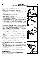
1) IMPORTANT! FAAC strongly recommends to follow these instructions
carefully for the safety of persons. Improper installation or misuse of
the product will cause very serious damages to persons.
2) Read the instructions carefully before installing the product.
3) Packaging materials (plastic, polystyrene etc.) are a potential hazard
and must be kept out of reach of children.
4) Keep these instructions for future reference.
5) This product has been designed and manufactured only for the use
stated in this manual. Any other use not expressly set forth will affect the
reliability of the product and/or could be source of hazard.
6) FAAC S.p.A. cannot be held responsible for any damage caused by
improper use or different from the use for which the automation system is
destined to.
7) Do not use this device in areas subject to explosion: the presence of
flammable gas or fumes is a serious hazard.
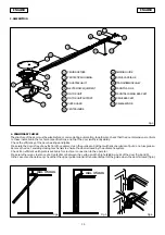
8) Mechanical constructive elements must comply with UNI 8612, CEN prEN
12604 and CEN prEN 12605 standards.
Countries outside the EC shall follow the regulations above besides their
national normative references in order to offer the utmost safety.
9) Faac cannot be held responsible for failure to observe technical stan-
dards in the construction of gates and doors, or for any deformation of
the gates which may occur during use.
10) Installation must comply with UNI8612, CEN pr EN 12453 and CEN pr EN
12635.
The degree of safety of the automation must be C+D.
10A) IEC 335-2-95
11) Before attempting any job on the system or operator, cut out electric
power and disconnect the batteries, if installed.
12) An omnipower switch shall be provided for the installation with an open-
ing distance of the contacts of 3 mm of more. Alternatively, use a 6A
EC MACHINE DIRECTIVE COMPLIANCE DECLARATION
(DIRECTIVE 89/392 EEC, APPENDIX II, PART B)
Manufacturer:
FAAC S.p.A.
Address:
Via Benini, 1 - 40069 Zola Predosa BOLOGNA - ITALY
Hereby declares that:
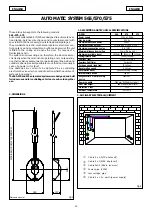
the 565/570/575 automation system
• is intended to be incorporated into machinery, or to be assembled with other machinery to constitute
machinery in compliance with the requirements of Directive 89/392 EEC, and subsequent amendments 91/
368 EEC, 93/44 EEC and 93/68 EEC;
• complies with the essential safety requirements in the following EEC Directives:
73/23 EEC and subsequent amendment 93/68 EEC.
89/336 EEC and subsequent amendments 92/31 EEC and 93/68 EEC.
and furthermore declares that unit must not be put into service until the machinery into which it is incorporated
or of which it is a component has been identified and declared to be in conformity with the provisions of
Directive 89/392 EEC and subsequent amendments enacted by the national implementing legislation.
Bologna, 1 January 1999
Managing Director
A.Bassi
thermomagnetic breaker with multi-pole switching.
13) Ensure that there is a differential switch up-line of the electrical system,
with a trip threshold of 0.03 A.
14) Check that the earthing plant is in perfect condition and connect it to
the metallic parts. Also earth the yellow/green wire of the operator.
15) The automation is fitted with an anti-crush safety system that is a torque
control device. In any case, further safety devices shall be installed.
16) The safety devices (e.g.photocells, safety edges, etc.) protect areas
where there is a
mechanical movement hazard,
e.g. crushing, entrap-
ment and cutting.
17) Each installation must be fitted with at least one flashing light (e.g. FAAC
LAMP, MINILAMP, etc.) as well as a warning plate suitably fixed to the
gate, besides the safety devices as per point 16 above.
18) Faac cannot be held responsible regarding safety and correct function-
ing of the automation in the event that parts other than Faac original
parts are used.
19) Use only Faac original spare parts for maintenance operations.
20) Do not carry out any modifications to automation components.
21) The installer must supply all information regarding manual operation of
the system in the event of an emergency and provide the end-user with
the ”End-user Guide” attached to the product.
22) Do not allow children or adults to stand near the product during opera-
tion.
23) Keep out of reach of children the remote radio controls and any control
devices. The automation could be operated unintentionally.
24) The end-user must avoid any attempt to repair or adjust the automation
personally. These operations must be carried out exclusively by qualified
personnel.
25) What is not explicitly stated in these instructions is not permitted.
IMPORTANT NOTICE FOR THE INSTALLER
GENERAL SAFETY REGULATIONS
Summary of Contents for 565
Page 15: ......


