


23
ENGLISH
ENGLISH
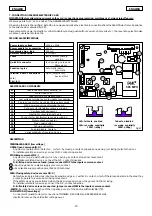
FUNCTION LOGICS
* Prevents closing if pulse is maintained
* Prevents closing and/or opening if pulse is maintained
Table 1 AUTOMATIC Logic
CLOSED
OPEN
CLOSING
LOCKED
OPENING
Closes
Open
Reverses motion
Locks
Closes
STOP
OPEN
SAFETY DEVICES
No effect**
Locks **
Locks **
No effect**
No effect
Reverses motion
No effect *
No effect *
OVERHEAD
DOOR
No effect**
No effect *
Table 2 SEMI-AUTOMATIC Logic
CLOSED
OPEN FOR
PAUSE
CLOSING
OPENING
Opens and
closes after the
pause time
Closes
STOP
OPEN
SAFETY DEVICES
No effect**
Locks *
Locks **
Locks **
No effect**
No effect
Restarts pause
time count*
Reverses motion
No effect *
No effect *
OVERHEAD
DOOR
LOCKED
Reverses motion
Restarts pause
time count*
No effect
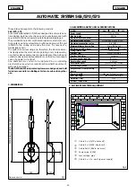
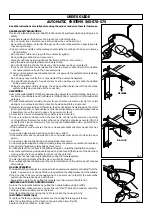
AUTOMATIC SET-UP
The set-up procedure is executed automatically just with a pulse.
MANUAL SET-UP
This procedure enables you to select the deceleration points, the
fully open point, and pause time.
AUTOMATIC SET-UP WITH LOGIC “E” (SEMI-AUTOMATIC)
Press and release the SET-UP push-button to select the logic.
After 8 seconds the operator effects a closing operation until a
stop is detected.
The operator now opens the door, and the opening movement
finishes when the mechanical stop is recognised.
The door is immediately closed.
The electronic appliance establishes the deceleration points.
If the SETUP procedure was
successful
, the courtesy lamp stays
lighted for 5 seconds. During this time, in order to reduce the load
on the release system, open pulses can be sent within 2 seconds
of each other to reverse the release carriage. A pulse equals
travel of 5 millimetres.
N.B.: the carriage can be seen to reverse only when the auto-
mated system is operating normally.
MANUAL SET-UP WITH LOGIC “E” (SEMI-AUTOMATIC)
Press and release the SET-UP push-button to select the logic.Carry
out the following procedure within 8 seconds after pressing the
SETUP push-button, otherwise the oprator will execute auto-
matic SETUP.
1
st
OPEN: the operator effects a closing operation until a stop is
detected.
2nd OPEN: the operator continues with an opening movement.
3rd OPEN: defines the point at which start of deceleration is
required.
4th OPEN: defines the end of the opening** movement.
5th OPEN: starts closing movement.
6th OPEN: defines the point at which start of deceleration is
required.
Allow the operator to reach the stop.
If the SETUP procedure was
successful
, the courtesy lamp stays
lighted for 5 seconds. During this time, in order to reduce the load
on the release system, open pulses can be sent within 2 seconds
of each other to reverse the release carriage. A pulse equals
travel of 5 millimetres.
N.B.: the carriage can be seen to reverse only when the auto-
mated system is operating normally.
AUTOMATIC SET-UP WITH LOGIC “A” (AUTOMATIC)
Hold down the SET-UP push-button to select the logic until the
courtesy light goes on (about 5 seconds).
After 8 seconds the operator effects a closing operation until a
stop is detected.
The operator now opens the door, and the opening movement
finishes when the mechanical stop is recognised.*
The door is immediately closed.
The electronic appliance establishes the deceleration points,
and pause time is fixed at 3 minutes.
If the SETUP procedure was
successful
, the courtesy lamp stays
lighted for 5 seconds. During this time, in order to reduce the load
on the release system, open pulses can be sent within 2 seconds
of each other to reverse the release carriage. A pulse equals
travel of 5 millimetres.
N.B.: the carriage can be seen to reverse only when the auto-
mated system is operating normally.
MANUAL SET-UP WITH LOGIC “A” (AUTOMATIC)
Hold down the SET-UP push-button to select the logic until the
courtesy light goes on (about 5 seconds).Carry out the following
procedure within 8 seconds after pressing the SETUP push-button,
otherwise the oprator will execute automatic SETUP.
1
st
OPEN: the operator effects a closing operation until a stop is
detected.
2nd OPEN: the operator continues with an opening movement.
3rd OPEN: defines the point at which start of deceleration is
required.
4th OPEN: defines the end of the opening movement and starts
the pause time count** (3 minutes max.).
5th OPEN: interrupts the pause time count and starts the closing
movement.
6th OPEN: defines the point at which start of deceleration is
required.
Allow the operator to reach the stop.
If the SETUP procedure was
successful
, the courtesy lamp stays
lighted for 5 seconds. During this time, in order to reduce the load
on the release system, open pulses can be sent within 2 seconds
of each other to reverse the release carriage. A pulse equals travel
of 5 millimetres.
N.B.: the carriage can be seen to reverse only when the auto-
mated system is operating normally.
* Otherwise, an OPEN pulse may replace the stop.
** Otherwise, the stop can be used during opening.
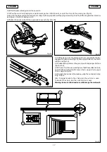
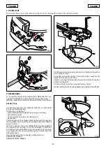
IMPORTANT: At set-up, if the operator does not effect any move-
ment when the OPEN push-button (see fig.34 ref. A) is pressed,
check that the housing is in correct position.
Summary of Contents for 565
Page 15: ......


