


13
ENGLISH
ENGLISH
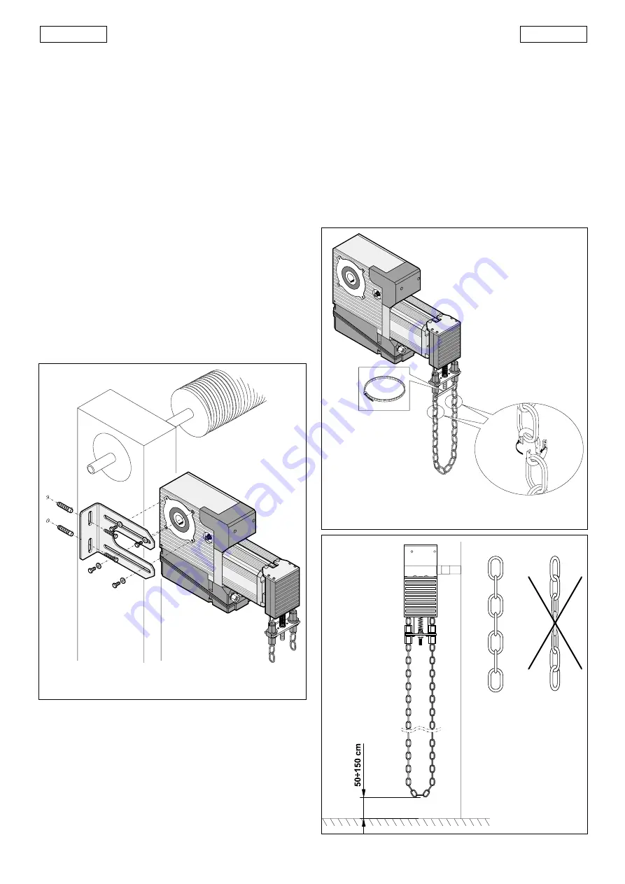
Fig. 8
5.3 INSTALLING THE OPERATOR
•Release the operator with the appropriate lever.
•Fit the securing plate on the operator without tightening the
screws.
•Engage the power take-off on the drive shaft.
•Position the operator (see paragraph 5.1) and rest the plate on
the support (wall or metal structure) on which you have decided
to secure it (see figure 7.).
•Tighten the screws without forcing them, while resting the plate
on the support.
•Trace the position of the installation holes.
•Remove the operator.
•Carry out the securing preparation work.
•Insert the first key securing bush and the key itself in the shaft
(see fig.2 ref. 8 and 9).
•Re-install the operator with the plate released.
•Secure the plate to the support, tighten the fastening screws
on the operator to a maximum torque of 18Nm and insert the
second key securing bush.
•Secure the two bushes after positioning them in contact with
the operator’s power take-off.
•Lock the operator.
If you wish to weld the securing plate to the support, do the
welding with the operator uninstalled, and protect the drive
shaft in the power take-off engagement zone. If the operator
cannot be removed, it must be protected.
Fig. 7
5.4 WINCH ADJUSTMENT
Fully unwind the supplied chain and unite one of its ends to the
one already inserted in the winch, using one of the supplied
chain links (see figure 8.).
Cut the chain to measure, preventing the lower part of the
“chain- loop” from touching the ground (see figure 9) and
assemble the other two ends of the chains.
Cut the service tie.
Adjust the screw of the balancing spring (see figure 10) so that
the winch support completely disappears inside the plastic
enclosure (see figure 11).
Make sure that the traction of just one of the chain branches
causes the winch to engage, and return to idle position on
being released.
Secure the fastening nut and make sure that operator activation
Fig. 9


