18
ENGLISH
ENGLISH
6. INSTALLATION
6.1 Find the mid-point of door and ceiling and mark the two lines with a highlighter.
6.2 Find the highest movement point of the door and mark this on the lintel.
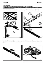
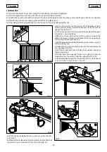
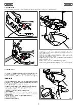
6.3 Position the securing bracket 5 mm above the line you had marked, which must be centered with respect to the door (fig.16).
6.4 Mark the two bracket securing points and drill the necessary holes.
6.5 Next, using screws and washers, screw the bracket on the expansion plugs (fig. 16).
Fig.19
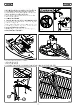
6.6 Place the operator on the ground, lift up the sliding longitu-
dinal member and step toward the bracket – fit the screw and
tighten the nut (fig. 17).
6.7 Lift up the operator, making sure it is horizontal with respect
to the door – use a spirit level.
6.8 When you have reached the correct position, measure the
distance between ceiling and operator so that you can shape
the securing brackets in advance.
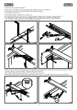
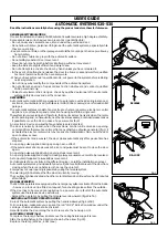
6.9 Fit the supplied brackets in the slots and secure the operator
with the nut (fig. 18).
6.10 Bend the securing brackets in line with the measurements
you had taken (fig. 19).
6.11 Lift up the operator, place it in its correct position, and mark
the securing holes.
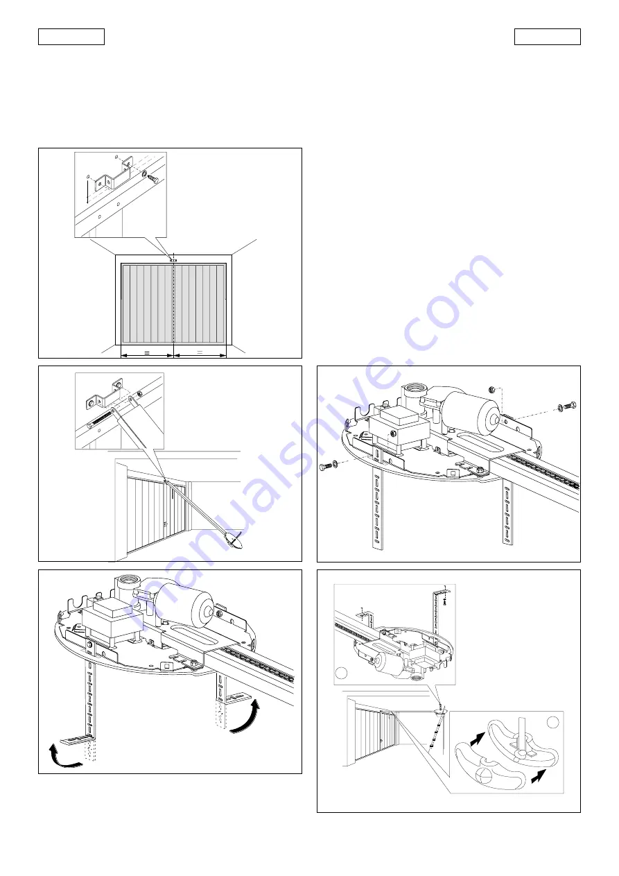
6.12 Drill, insert the expansion plugs and, using screws and
washers, secure the motor unit to the ceiling (fig. 20 ref. A).
6.13 First establish the height of the release knob, cut off excess
cord, and make a knot on the cord end.
Fig.16
5 mm
Fig.17
6.14 Place the knot inside the knob – as shown in fig. 20 ref. B –
and close it.
6.15 If using the central support guide, shape the brackets, lock
them with a nut and secure them to the ceiling (fig. 21).
Fig.18
Fig.20
A
B

