


7
455 D Control Board
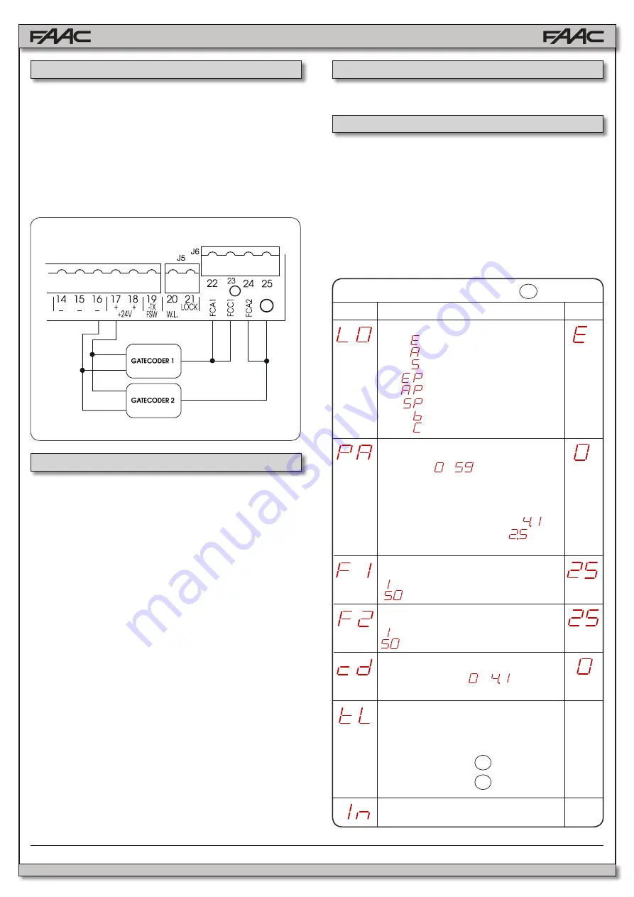
= Semi-automatic
= Automatic
= “Safety” Automatic
= “Stepped” Semi-automatic
= “Stepped” Automatic
= “Safety Stepped” Automatic
= “B” Semi-automatic
= Dead-man
FC
C
2
RED
RED
BLACK
BLACK
WHITE
WHITE
LEAF 1 FORCE:
Adjusts thrust of Motor 1.
= minimum force
= maximum force (hydraulic)
press
F
Figure S
The following table displays the sequence of functions
accessible in BASIC PROGRAMMING:
BASIC PROGRAMMING
PAUSE TIME:
This has effect only when automatic logic is selected.
Adjustable from to
secs. in one-second
increments.
Subsequently, display changes to minutes and tenths
of seconds (separated by a decimal point), time
is adjusted in 10-second increments, up to
minutes max. Thus, if the unit displays
, Pause
Time is 2 mins. and 50 secs.
Exit from programming and return to inputs status
monitoring.
These inputs are designed for connection of opening
and closing limit-switches or Gatecoders
The 400 operator cannot use limit switches but only
Gatecoders. They are used to detect the leaf’s angular
position and to thus obtain deceleration and stop
positions more accurately than using the operating
timing.
Please refer to Figure S for wiring information. If the
Gatecoders are not used the J6 inputs can be left
unconnected.
To program the 455D Control Board, you have to access “
PRO-
GRAMMING
” mode. Programming is split into two parts:
BASIC
and
ADVANCED
.
LEAF 2 FORCE:
Adjusts thrust of Motor 2.
= minimum force
= maximum force (hydraulic)
LEAF 1 CLOSING DELAY:
Delays closing start of leaf 1 with respect to
leaf 2. Adjustable from to
minutes (see
Pause Time).
TIME LEARNING (see Section F.3.):
Enables the selection between “simple”
(automatic) learning and “complete” (manual
choice of deceleration and stop points) learning.
+
≈
1 s.
Simple Learning:
>
3 s.
Complete Learning:
OPERATING LOGICS (see tab. 3/a - h):
If using hydraulic operators, set force to maximum level.
1.4.7 Terminal Block J6 - Limit-Switch or Gatecoder
1.5.1 Basic Programming
To access BASIC PROGRAMMING, press key
F
:
•
Press and hold
F
, the unit will display the name of the first func
-
tion / parameter.
•
When you release the key, the unit will display the parameter’s
current value.
• Value can be modified with keys
+
and
-
.
•
Press and hold
F
again, the unit will display the name of the next
function / parameter.
•
When you reach the last function, press
F
to exit the program,
the display resumes monitoring input status.
Display
Function
Default
1.5 Programming
+
This is a brief description of the main operating logics of the
system. For a complete description please refer to Table 3
•
A (automatic): The gate opens on command and auto-
matically closes after a pause phase. A second com-
mand while opening is ignored; a second command dur-
ing the pause phase interrupts the pause time; a second
command during closing reopens the gate. A maintained
open command will hold the gate open.
•
S (security): The security mode is like A logic except that
a second command during opening immediately closes
the gate. A maintained open command will not hold the
gate open.
•
E (semi-automatic): This mode requires a second com-
mand during opening stops the gate. A second command
during closing reopens the gate.
•
EP (semi-automatic, step by step): This mode requires
a command to open and a command to close. A second
command during opening or closing causes the gate to
stop. A third command then reverses the previous motion
of the gate.
•
B (manned, pulsed): This mode is designed for guard
station use and requires a three button switch (pulsed) to
open, close, and stop the gate.
•
C (manned and constant): This mode requires constant
pressure switches. One to open and one to close. No
pressure on a switch stops the gate.
1.4.8 Operating Logics
(800) 878-7829
www.FastGateOpeners.com


