


400 P
ARTS
L
IST
Page 13
November, 2003
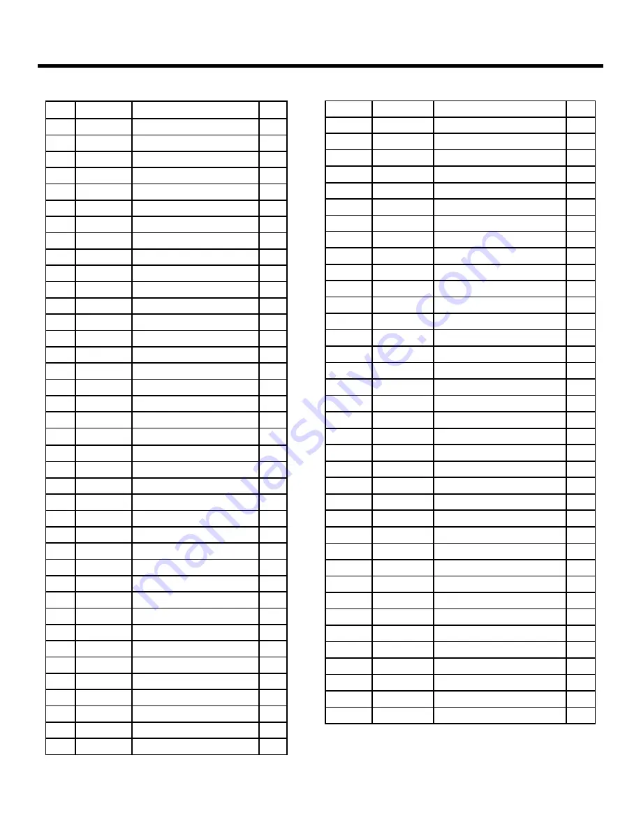
400 Operator And
455 D Control Panel Installation Manual
POS PART NO.
DESCRIPTION
QTY
1
2036
Galvanized Nut (8mm)
1
2
7220015
Rear Bracket
1
3
7284005
Rear Bracket Plate
1
4
7182075
Short Pin
1
5
7221115
Rear Fork
1
6
2037
Self-Locking Nut (8mm)
1
7
7170865
Rear Flange
1
8
7099101
Gasket (D80)
2
9
7090440
O-Ring Locking Cap (Small)
2
10
7090655
O-Ring Locking Cap (Center)
1
11
41850215
Locking Cap
1
12
7094065
Gasket (copper)
3
13
2274
Vent Screw (4x6mm)
3
14
7270805
Locking Cap Cover
1
15
7270815
Access Slide (Locking Cap)
1
16
7131005
Viro Key (Manual Release)
1
17
N/A
Self Threading Screw (4mm)
1
18
7119475
Vibration Dampener
2
19
2365
Motor Bolt (4X50mm)
4
20
2366
Lock Washer (4mm)
4
21
2367
Hex Nut (4mm)
4
22** 77000425
115V 1400 RPM Motor
1
23
7119485
Vibration Dampener
2
24
309003
Operator Body
1
25
N/A
Vent Screw Label
1
26
7182175
Long Pin
1
27
2274
Vent Screw (4x6mm)
3
28
N/A
Socket Head Screw (5X20mm)
8
29
7514055
Electric Power Cord
1
30* 2581
Fiber Washer
1
31* 7039305
Strain Relief Brass Washer
1
32* 7109155
Strain Relief Nut
1
33* 7109145
Strain Relief
1
34
3204395
1Lt Lobe Pump
1
35
N/A
Pump Pin (4X28mm)
2
36
7039025
Washer (Swivel)
1
37
702201
Swivel Jam Nut (10mm)
1
38
7073025
Swivel Joint
1
39
N/A
Star Washer (5mm)
2
POS
PART NO.
DESCRIPTION
QTY
40
7119405
Protective Cover End Cap Plug
2
41
7019195
Tie-Rod (Protective Cover)
2
42
4170015
Protective Cover End Cap
1
43
7272105
Protective Cover
1
44
7220355
Front Mounting Bracket
1
45
7090010015 O-Ring
3
101
7090010015 O-Ring
5
102
7049135
Valve Retainer
2
103
4404065
Inlet Valve
2
104
4180035
Red By-Pass Cap Assembly
1
105
4180045
Green By-Pass Cap Assembly
1
106
7119015
By-Pass Cap (Red)
1
107
7210025
By-Pass Spring
2
108
7310315
By-Pass Cap
2
109
7119115
By-Pass Cap (Green)
1
110
7090280015 O-Ring Retract Tube (Short)
3
111
7043055
Extrusion Ring
1
112
4180195
Manual Release
1
113
7090360
O-Ring (Valve Body)
1
114
7361335
Retract Tube
1
115
N/A
O-Ring Front Flange (Internal)
1
116
4994265
Front Flange
1
117
4350105
Piston Assembly
1
118
7091015
Piston Rod Packing
2
119
7366025
Cylinder
1
120
7090300
O-Ring (Shuttle Piston)
1
121
4404085
Lock Valve
2
122
4180285
Shuttle Piston
1
123
N/A
Star Washer (5mm)
4
124
7230295
Tie-Rod (Cylinder)
4
125
4994345
Valve Body (CBAC)
1
126
N/A
Guide Ring (Piston)
1
127
7049005
Valve Retainer (Brass)
2
128
7090675
O-Ring (Retract Tube)
2
129
3905265
Skin Pack
1
130
2167*
Seal Kit
1
131
6105
1 Qt Monolec Oil
1
∗
Included in Kit #2167A*
∗
* 220V 1400RPM Motor Part #77000415


