background image

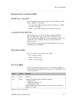
Removing and Replacing a Power Supply

ARX

®

6000 Hardware Installation Guide

B - 7

Removing and Replacing a Power Supply

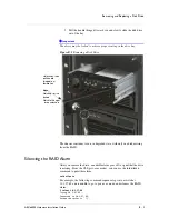
Remove a power supply as described in 

Removing the Power Supplies

, on 

page 6-7. To replace a power supply, reverse the steps.

DANGER

A chassis configured with two power supplies has two power cords. In the 
event that AC power must be removed from the system, disconnect both 
power cords before servicing the unit. Otherwise, the power-supply units 
keep a charge for 10-15 minutes, and you could get an electric shock by 
touching the pins on the back.

Removing and Replacing the Air Filter

WARNING

Customers are required to maintain the switch’s air filter at regular 
intervals. Failure to do so may damage the switch.

To remove and replace the air filter:

1. Remove the air-filter front panel/cable guide by loosening the two 

captive screws on either side of the panel (see 

Air Filter and Cable 

Management

, on page 6-13.) Be careful to keep cabling intact.

2. Slide the air filter out of the chassis and replace with a new air filter. 

3. Reinstall the air-filter panel/cable guide over the air filter opening 

by aligning the holes and tightening the captive screws. 

Summary of Contents for ARX 6000

Page 1: ...ARX 6000 Hardware Installation Guide 810 0001 00 ...

Page 2: ......

Page 3: ...ut F5 s express written consent Patents This product has several patents pending Export Regulation Notice This product may include cryptographic software Under the Export Administration Act the United States government may consider it a criminal offense to export this product from the United States RF Interference Warning This is a Class A product In a domestic environment this product may cause r...

Page 4: ... Fellows of Harvard University All rights reserved Copyright c 1998 2004 The OpenSSL Project All rights reserved Unless otherwise noted the companies organizations products domain names e mail addresses logos people places and events depicted in examples herein are fictitious No association with any real company organization product domain name e mail address logo person place or event is intended...

Page 5: ...Table of Contents ...

Page 6: ......

Page 7: ...2 4 Switch Management 2 4 Supported Protocols 2 5 Network 2 5 File Services 2 5 Security and Authentication 2 5 Management 2 6 3 Chassis Hardware Chassis Components 3 3 Power Supply 3 3 Disk Drives 3 4 Fan Tray Module 3 5 Chassis Configurations 3 6 Redundant Pairs 3 7 Resilient Overlay Network RON 3 7 4 Hardware Modules System Control Module SCM 4 3 Features 4 4 Dual Channel SCM 4 4 Adaptive Servi...

Page 8: ...Installing the Air Filter Panel and Cable Guide 6 14 7 Connecting the Switch to the Network Management Interfaces 7 3 Connecting the Console Terminal 7 3 Booting the Switch 7 4 Sample Booting a Non Replacement Switch 7 4 Preparing for Switch Replacement 7 6 Installing a Redundant Peer or Cluster 7 9 Sample Replacing a Redundant Peer 7 11 Connecting the Ethernet Management Port 7 14 8 Maintenance P...

Page 9: ...x Removing and Replacing Modules B 3 Removing and Replacing a Disk Drive B 4 Silencing the RAID Alarm B 5 Replacing the Disk Drive B 6 Removing and Replacing the Fan Tray B 6 Removing and Replacing a Power Supply B 7 Removing and Replacing the Air Filter B 7 ...

Page 10: ...Table of Contents x ...

Page 11: ...X 6000 and its hardware components It also describes how to install the switch and connect it to the network This chapter contains the following sections Audience for this Manual Document Conventions Related Documents Safety and Regulatory Notices Contacting Customer Service ...

Page 12: ......

Page 13: ...entions This manual uses the following conventions when applicable courier text represents system output bold text represents user input italic text appears for emphasis new terms and book titles Note Notes provide additional or helpful information about the subject text Important Important notices show how to avoid possible service outage or data loss WARNING Warnings are instructions for avoidin...

Page 14: ...vailable ARX 6000 Quick Installation ARX 500 Hardware Installation Guide ARX 1000 Hardware Installation Guide ARX 2000 Hardware Installation Guide ARX 4000 Hardware Installation Guide ARX GUI Quick Start Network Setup ARX CLI Reference ARX CLI Network Management Guide ARX CLI Storage Management Guide ARX CLI Maintenance Guide ...

Page 15: ...r Class A ITE Label This is a Class A product based on the standard of the Voluntary Control Council for Interference by Information Technology Equipment VCCI If this equipment is used in a domestic environment radio disturbance may occur in which case the user may be required to take corrective actions Qualified Personnel Warning WARNING Only trained and qualified personnel should be allowed to i...

Page 16: ...onnel through the use of a special tool lock and key or other means of security and is controlled by the authority responsible for the location ATTENTION Cet appareil est à installer dans des zones d accès réservé Ces dernières sont des zones auxquelles seul le personnel de service peut accéder en utilisant un outil spécial un mécanisme de verrouillage et une clé ou tout autre moyen de sécurité L ...

Page 17: ...onstitue la seule unité montée en casier elle doit être placée dans le bas Si cette unité est montée dans un casier partiellement rempli charger le casier de bas en haut en plaçant l élément le plus lourd dans le bas Si le casier est équipé de dispositifs stabilisateurs installer les stabilisateurs avant de monter ou de réparer l unité en casier Power Power Cord Usage WARNING Do not use the attach...

Page 18: ...ION Les ports étiquetés LINK 1 1 through 1 6 CONSOLE MGMT MIRROR et DEBUG sont des circuits de sécurité basse tension safety extra low voltage ou SELV Les circuits SELV ne doivent être interconnectés qu avec d autres circuits SELV Circuit Breaker 15A WARNING This product relies on the building s installation for short circuit overcurrent protection Ensure that a fuse or circuit breaker no larger t...

Page 19: ...acturer s instructions ATTENTION Danger d explosion si la pile n est pas remplacée correctement Ne la remplacer que par une pile de type semblable ou équivalent recommandée par le fabricant Jeter les piles usagées conformément aux instructions du fabricant International Power Cord Requirements International cords should have the following characteristics maximum length 4 5 m 15 feet Female End IEC...

Page 20: ...a under the harmonized FCC DOC EMI requirements Equipment Requirements for units imported into Canada shall bear both English and French translations as follows This digital apparatus does not exceed the Class A or B limits for radio noise emissions from digital apparatus set out in the Radio Interference Regulations of the Canadian Department of Communications This Class A or B digital apparatus ...

Page 21: ...works Customer Service F5 Networks Online Knowledge Base Online repository of answers to frequently asked questions http support f5 com F5 Networks Services Support Online Online customer support request system https websupport f5 com Telephone Follow this link for a list of Support numbers http www f5 com training support cust omer support contact ...

Page 22: ...Chapter 1 1 12 ...

Page 23: ...2 Product Overview This chapter provides a general overview of the F5 ARX 6000 Topics include the following The ARX Redundancy Features Switch Management Supported Protocols ...

Page 24: ......

Page 25: ...tch consists of a 6 slot chassis that accommodates a system management and control module and a family of service modules that support Fast Ethernet and Gigabit Ethernet interfaces for connectivity to network infrastructure network attached storage NAS devices and file servers with direct attached storage DAS The switch s 80 Gbps aggregate switching capacity ensures non blocking throughput for all...

Page 26: ... to the secondary switch Redundant Array of Independent Disks RAID Level 1 protected boot configuration disk drives Redundant power supplies installed share the power load Redundant connections to the fan tray Redundant AC DC power See Chapter 3 Chassis Hardware for more information about these chassis components Switch Management For local and remote management the ARX 6000 provides the following...

Page 27: ...ibility mode This allows inter operability with legacy 802 1D only devices VLAN 802 1Q passive link aggregation 802 3ad without LACP Internet Protocol IP Transmission Control Protocol User Datagram Protocol TCP UDP Domain Name Service DNS as a client Network Time Protocol NTP as a client File Services Common Internet File System CIFS Network File System NFS NFSv2 over UDP and NFSv3 over TCP or UDP...

Page 28: ... Protocol over SSH HTTPS SOAP based API over HTTP and or HTTPS For transferring maintenance and release files File Transfer Protocol FTP Trivial File Transfer Protocol TFTP Secure Copy SCP NFS for transfers to or from an ARX volume CIFS for transfers to or from an ARX volume Simple Mail Transfer Protocol SMTP for sending email notices of trouble conditions ...

Page 29: ...ware configuration Topics include the following Chassis Components Chassis Configurations Redundant Pairs Resilient Overlay Network RON This chapter describes chassis hardware only For information about hardware modules management and service modules see Chapter 4 Hardware Modules ...

Page 30: ......

Page 31: ...rvice modules in a system configured for 220V power All modules are field replaceable The chassis is shipped with all components installed per customer order Components include all management and service modules power supplies disk drives and fan tray includes six fans The chassis utility bay accommodates two system disk drives and up to two power supplies Figure 3 1 Chassis Front View Power Suppl...

Page 32: ...ndicators per power supply unit Power Fail and over temperature alarms displayed on system console Hot swappable and front accessible components See for power requirements and specifications Figure 3 2 Disk Drive and Power Supply Locations Disk Drives The switch requires two system disk drives for operation Together the two disk drives provide RAID Level 1 redundancy The drives contain software im...

Page 33: ...isk drives provide three status LEDs Red indicates Activity Green indicates Power Orange indicates Failure Fan Tray Module The chassis fan tray module is an environmentally controlled fan system with an intelligent fan controller The fan tray contains six individual fans and is located at the top of the chassis refer back to in Figure 3 1 on page 3 3 The hot pluggable fan tray containing six fans ...

Page 34: ...fan tray communication Chassis Configurations The ARX 6000 can accommodate up to six modules in its chassis and these modules can be configured to maximize throughput or to maximize high availability between switches The switch currently supports one management module SCM in slot 1 and service modules NSM and ASM in any order or combination in the service module slots Most configurations require a...

Page 35: ...initial boot procedure The differences are outlined later in Chapter 7 Connecting the Switch to the Network Resilient Overlay Network RON You can connect multiple ARX es together in a Resilient Overlay Network RON A RON is composed of a series of IP tunnels between the switches You can use the CLI to configure a RON tunnel as described in the CLI manuals See the ARX CLI Network Management Guide an...

Page 36: ...Chapter 3 Chassis Hardware 3 8 ...

Page 37: ...tures functions and front panel interfaces For information about module connectors and pinout assignments see Appendix A Cable Connectors ARX 6000 modules include the following management and service modules System Control Module SCM Adaptive Services Module ASM Network Services Module NSM ...

Page 38: ......

Page 39: ...chassis The SCM communicates with the slots in the chassis over a system status bus which enables the SCM to manage monitor and control module activity The SCM also provides switch fabric functionality in the chassis Figure 4 1 SCM Front Panel Alert and Status LEDs See Chapter 8 for LED information Mirror port RS 232 Serial console port RJ 45 Link status LEDs 10 100 Ethernet management port RJ 45 ...

Page 40: ...synchronization for modules Gathering and monitoring of module health status and statistics through LEDs and software Module insertion removal in a slot Environmental Control and Management The SCM also manages or monitors the following functions Temperature changes in the chassis and for each module Module resets for example if a module s temperature gets too high or power down operation Power dr...

Page 41: ...functions Virtual distribution of file services for NFS v2 v3 and CIFS protocols Dynamic adapting of the directory structure of back end filers based on data management policies Back end file storage device NAS and DAS aggregation Namespace and volume management Network Services Module NSM The Network Services Module NSM provides network connectivity and supports load balancing resource switching ...

Page 42: ... NSM TX Figure 4 2 shows the NSM TX module front panel which provides six RJ 45 connections Figure 4 2 NSM TX Front Panel Alert and Status LEDs See Chapter 8 for LED information Ports 1 6 Link status LEDs Ports 1 6 RJ 45 connectors ...

Page 43: ... reach distances up to 500m over 50 125um MMF Figure 4 3 NSM FX Front Panel Features The NSM provides or supports the following features and functions Network connectivity Auto negotiation for 100 1000 Ethernet transmission Standard Ethernet and jumbo frame 9K packet sizes Alert and Status LEDs See Chapter 8 for LED information Ports 1 6 Ethernet port Link status LEDs Ports 1 6 small form factor p...

Page 44: ...es for Layer 2 processing Low latency store and forward switching with built in multicast support Resource switching Network File System NFS fast path Common Internet File System CIFS fast path NFS client connection aggregation to direct network attached storage NAS ...

Page 45: ...ts and cable requirements for the ARX and its components This chapter also describes regulatory information Topics include System Specifications System Power Requirements Power Cord and Cable Requirements Regulatory Compliance FCC Compliance See Appendix A for cable connector diagrams and pinouts ...

Page 46: ......

Page 47: ...149 deg F 20 deg to 65 deg C Power Supply Power Input voltage 220 Vac Output voltage 48 Vdc 3000 W maximum total DC power per chassis Note only 1500 W power is used the 3000 W accounts for redundant power supplies Due to the 88 efficiency of the drives 1704 W input is required to achieve the maximum 1500 W output Fan Tray Dimensions includes outer bezel Height 4 88 in 12 40 cm Width 17 25 in 43 82...

Page 48: ...ll of the above divided by 0 88 the power supply runs at 88 efficiency Specifically Hardware module dimensions SCM ASM NSM Height 15 25 in 38 74 cm Width 1 75 in 4 45 cm Depth 20 in 50 8 cm Hardware module power SCM ASM NSM See Table 5 2 for power consumption information Input voltage 48 Vdc Component Power Watts Typical Maximum System Control Module SCM 160 W 179 W Network Services Module NSM 125...

Page 49: ... 45 connector System Control Module SCM MGMT port Mirror port 6 per NSM Ethernet cables for connection to 100 1000 Mbps Ethernet RJ 45 connectors 6 port Network Services Module NSM copper version a 100 1000BASE T Category 5 6 unshielded twisted pair UTP cable 24 AWG a NSM Gigabit Ethernet ports support automatic MDI MDIX cross over This feature automatically corrects the polarity of the attached C...

Page 50: ...tal device pursuant to part 15 of the FCC Rules These limits are designed to provide reasonable protection against interference when the equipment is operated in a commercial environment This equipment generates uses and can radiate radio frequency energy and if not installed and used in accordance with the instruction manual may cause harmful interference to radio communications Operation of this...

Page 51: ...ics and tasks Safety Instructions Required Tools and Equipment Verifying Shipment Unpacking the Chassis Removing the Fan Tray Rack Mounting the Chassis Installing the Front Bezels Attaching the Power Cords Powering Up the Chassis Cabling the Modules Air Filter and Cable Management ...

Page 52: ......

Page 53: ...and make sure it is set to OFF Disconnect any power or external cables before moving a chassis A chassis configured with two power supplies has two power cords In the event that AC power must be removed from the system disconnect both power cords before servicing the unit to avoid electric shock Required Tools and Equipment The following equipment is required recommended for unpacking rack mountin...

Page 54: ...ents Chassis ARX 6000 chassis with installed components fan tray modules two power supplies two disk drives air filter cable guide Accessory Kit Front bezels cover fan tray and utility bay 2 20A 250V power cords Console cable 8 ft with RJ 45 to DB9 adapter Keys for unlocking disk drives Air filter front panel cable guide ARX 6000 rack mount alignment template long white stickers ARX 6000 Quick Ins...

Page 55: ... Figure 6 1 Chassis Shipping Carton Unpack the chassis as follows 1 Using a handcart or pallet jack move the shipping carton to the installation site DANGER With packaging a minimally configured chassis weighs approximately 163 lb 150 lb without packaging Two or more people are required to move lift and rack mount the chassis 2 Before unpacking the chassis inspect the carton for any shipping damag...

Page 56: ...which sits in foam packaging on the pallet 7 Remove the foam packaging from the bottom front and back of the chassis Before you install the chassis into a rack it is recommended that you remove the fan tray and power supplies to facilitate handling and ease rack mounting These components are particularly heavy You can replace these units after the chassis is secured in the rack as shown in the nex...

Page 57: ...tray grasp the handle and slowly pull the fan tray toward you see Figure 6 2 Figure 6 2 Removing Fan Tray 2 Carefully slide the fan tray out of the top of the chassis and set aside Removing the Power Supplies The chassis contains two power supplies that are accessible from the front panel The top power supply is called power supply A in the CLI s show chassis chassinfo command The bottom power sup...

Page 58: ...efully inserting a flat head screwdriver into the center notch and pulling up and out The power supply handle will release toward you Figure 6 3 Removing the Power Supply WARNING Do not put excessive strain on the handle Do not lift or carry the power supply by its handle 2 Carefully slide the power supply out of the bay and set aside 3 If there is a redundant power supply repeat these steps to re...

Page 59: ... and align the six holes on each side of the chassis flange edges with the holes in the rack See Figure 6 4 Use the alignment templates as a guide Figure 6 4 Aligning Chassis Flange with Rack 1 Insert 1 inch 2 5 cm Phillips head screws six on each side through the holes and tighten securely 2 When the chassis is secured in the rack replace the fan tray and power supply or power supplies Reverse th...

Page 60: ...of bezel with the pins on the fan tray Figure 6 5 Fan Tray Bezel 2 Using two hands gently press the bezel squarely onto the pins until the bezel clicks into place over the fan tray Utility Bay 1 Align the bezel over the utility bay holding the bezel by the indentation on the left side for an easier grip Bezel Pins 2 each side ...

Page 61: ... clicks into place top and bottom Attaching the Power Cords To attach the AC power cords to the chassis 1 Locate the power ON OFF toggle switches on the back of the chassis and ensure they are set to the OFF position 2 For a chassis with only one power supply attach the power cord to the right plug 3 For a chassis with two power supplies attach a power cord to each plug Bezel Pins upper and lower ...

Page 62: ...a risk of electric shock Figure 6 6 Power Switch and Connections See Power Cord and Cable Requirements on page 5 5 for power cord and cable specifications Powering Up the Chassis Note The switch requires a dedicated 20A circuit for each AC DC power supply WARNING Before applying power ensure that the AC outlet to the switch is properly grounded To power up the chassis find both ON OFF toggle switc...

Page 63: ...pter 7 Connecting the Switch to the Network Module cables except the console cable are supplied by the customer For cable specifications and requirements for each of the module types see Power Cord and Cable Requirements on page 5 5 describes cable connector and pinout information Air Filter and Cable Management The chassis is shipped with the air filter installed The accessory kit contains the ai...

Page 64: ... to do so may damage the switch To install the air filter panel cable guide 1 Remove the air filter front panel cable guide from the accessory kit 2 Remove the tape from the air filter opening and verify the air filter is seated properly in the chassis 3 Insert the cable guide into the opening aligning the captive screws on either side with the holes in the chassis 4 Hold one side while tightening...

Page 65: ...is chapter describes how to connect the ARX to a console terminal and boot the switch for the first time Topics and tasks include Management Interfaces Connecting the Console Terminal Booting the Switch Connecting the Ethernet Management Port ...

Page 66: ......

Page 67: ...out of band OOB management station During the initial boot process described in this chapter you can only access the serial Console port You configure the OOB management port MGMT as part of the procedures in this chapter Connecting the Console Terminal Set the following console terminal parameters to match those on the SCM s Console port 9600 baud rate default XON XOFF flow control 8 data bits 1 ...

Page 68: ...ons as they come up Examples and instructions appear in the subsections below Sample Booting a Non Replacement Switch This sample shows the simplest initial boot scenario for a new non replacement switch that is either standalone or the first member of a redundant pair The sample answers are not necessarily appropriate to the following scenarios this replaces a defunct switch this will join a runn...

Page 69: ...ss and mask 3 Enter the management port IP address in the format nnn nnn nnn nnn or none 10 1 27 69 4 Enter the management port subnet mask in the format nnn nnn nnn nnn default 255 0 0 0 255 255 255 0 The switch s management port requires a gateway IP address 5 Enter the gateway IP address for the management interface in the format nnn nnn nnn nnn or none default 10 1 1 1 10 1 27 1 A switch repla...

Page 70: ...me and password that you entered in the initial boot script For example User Access Authentication Username admin Password mypassword SWITCH The switch is now ready for configuration through the GUI or the CLI See the ARX GUI Quick Start Network Setup manual for instructions on using the GUI to set up network parameters or the ARX CLI Network Management Guide for detailed network configuration ins...

Page 71: ...r example A switch replacement requires additional configuration questions 6 Are you doing a switch replacement in the format yes or no default no yes Matching the Private Subnet The next set of questions ask for the switch s private subnet the private VLAN for that subnet and the VLAN for a private metalog subnet If the failed switch was in a redundant pair and or RON network the private subnets ...

Page 72: ...rmat integer 1 4095 default 1003 1009 Enter Finding the UUID of the Failed Switch When a switch imports storage from back end filers it marks each share with its Universally Unique ID UUID A replacement switch must use the same UUID or it rejects all of the shares used by its predecessor You also need to set the UUID if the switch is brought back to its factory defaults a Manufacturing Installatio...

Page 73: ... for the UUID Enter the UUID of the failed switch For example The UUID should only be entered if this chassis is replacing a failed chassis and the entered UUID should match the UUID of the failed chassis 11 Enter the chassis s UUID in the format xxxxxxxx xxxx xxxx xxxx xxxxxxxxxxxx default d4ukjce8 1854 11d8 91e3 f48e42637d58 3d17e8ce 571e 11dc 9852 ef323fbb290f Important No two running chassis s...

Page 74: ...tch This command outputs a base64 encoded string that is the encrypted master key Save this string and the wrapping password that you set in the command For example this shows the master key on a switch named minturnB minturnB show master key Master Key System Password uper ecretpw Wrapping Password an0ther ecretpw Validate Wrapping Password an0ther ecretpw Encrypted master key 2oftVCwAAAAgAAAApwa...

Page 75: ...nn default 255 0 0 0 255 255 255 0 The switch s management port requires a gateway IP address 5 Enter the gateway IP address for the management interface in the format nnn nnn nnn nnn or none default 10 1 1 1 10 1 27 1 This next question invokes the questions for switch replacement A switch replacement requires additional configuration questions 6 Are you doing a switch replacement in the format y...

Page 76: ...undant peer The master key is used to encrypt critical security parameters 15 Enter the master key in the format base64 encoded key or keyword generate default generate 2oftVCwAAAAgAAAApwazSRFd2ww H1pi7R7JMDZ9SoIg4WGA XsZP HcXjsIAAAADDRbMCxE bc The wrapping password in use to encrypt and decrypt the master key 16 Enter the wrapping password in the format text 6 28 characters an0ther ecretpw Confir...

Page 77: ...5 02 000 12535 Feb 5 2010 18 16 05 nbuilds SWITCH Database version 502000 21 SWITCH Generated running config Sun Feb 14 01 44 06 2010 SWITCH System UUID 3d17e8ce 571e 11dc 9852 ef323fbb290f SWITCH ip private vlan internal 1008 metalog 1009 subnet 169 254 17 0 255 255 255 0 SWITCH resource gateway 2 SWITCH SWITCH vlan SWITCH config SWITCH vlan 81 SWITCH description personnel dept SWITCH members 4 1...

Page 78: ...aphical User Interface GUI or the Command Line Interface CLI To access the GUI direct a web browser to the interface over HTTPS for example https 10 1 27 69 Use the crypto officer username and password entered above to log in For the CLI use SSH with the interface and the crypto officer username for example ssh admin 10 1 27 69 The ARX GUI Quick Start Network Setup manual contains instructions for...

Page 79: ...e ARX 6000 manual power down sequence as well as describing the hardware power on self test POST diagnostics and module status indicators LEDs and their associated conditions Powering Down the ARX 6000 POST Diagnostics LED Status Indicators ...

Page 80: ......

Page 81: ...to verify their basic hardware integrity You can view any hardware failures at the system console through the show version and show chassis commands See the following sample output Figure 8 1 Show Version Sample minturnA show version Copyright c 2002 2010 by F5 Networks Inc All rights reserved Running Release test1 rel Version 5 02 000 12535 Feb 5 2010 18 16 05 nbuilds Armed Release test1 rel Vers...

Page 82: ...ls Disk Status Verification Mode Verification Rate 1 Optimal Automatic 10 Disk Details Disk Size State Transfer Rate Model Bay 1 68 50G Online 320MB sec ATLAS10K4_73SCA Bay 2 68 50G Online 320MB sec ATLAS10K4_73SCA RAID Controller Details Rebuild Rate Max Transfer Rate Firmware RAID Alarm 90 320MB sec 1L49 G500 Enabled Slot Environment Slot Type State Power Temperature NVR Battery Drive 1 SCM Onli...

Page 83: ...A 2 67 N A 20 10 Gbps 4 67 N A N A Port Media Details Slot Port Type Vendor Status Disk Usage Name Total MB Used MB Free MB Used System 3173 1401 1610 47 Releases 5285 2681 2335 54 Logs 30037 56 28455 1 Cores DiagInfo Lists 8458 162 7866 3 Scripts 3172 178 2833 6 Reports 8458 33 7994 1 Temperature Details Sensor 1 C Sensor 2 C Sensor 3 C Sensor 4 C Slot Module Local Remote Local Remote Local Remot...

Page 84: ...less all POST tests pass If it persists indefinitely POST tests must have failed In the latter case you may need to replace the module module replacement procedures appear in an appendix of this manual Off Green Blinking Boot POST tests passed The module is running internal diagnostics and then booting Downloading the module s processor s are downloading new software and or firmware This state onl...

Page 85: ...ink is established There is no Activity LED for the client server ports The Link LED is over each Ethernet port in the NSM TX but it is under each Fibre port in the NSM FX Disk Drive LEDs The system disk drives provide three status LEDs Red indicates Activity Green indicates Power Orange indicates Failure Fan Tray LEDs The fan tray module front panel provides two status LEDs ALERT top and STATUS b...

Page 86: ... the fan tray as described in the appendix Red Green SCM to fan tray communication failure This indicates a failure of the fan controller in the fan tray Replace the fan tray as described in the appendix ALERT STATUS Condition Table 8 2 Fan Tray Status LEDs Continued ...

Page 87: ...A Cable Connectors ARX 6000 Connectors Console Connector and Pinouts SFP Optical Connector ...

Page 88: ......

Page 89: ...NSM Gigabit Ethernet ports support automatic MDI MDIX cross over This feature automatically corrects the polarity of the attached CAT5 cable regardless if it is a cross over or straight through type However for this feature to work the port must be set to auto negotiate enabled When the port speed duplex is forced auto negotiate is disabled automatic MDI MDIX cross over is disabled and you must ca...

Page 90: ...gure A 2 RJ 45 to Serial DB9 Adapter Table A 2 lists the RJ 45 pinout assignments for the rollover cable and the adapter The left column shows the transmit TxD ground GND and receive RxD signals and the right column shows the signals reversed at the console device The intervening columns show the pins that carry each of those signals SCM ACM Console Port RJ 45 Rollover Cable RJ 45 to DB9 Adapter C...

Page 91: ...igure A 3 SFP Optical Connector WARNING Fiber optic ports are shipped with cable connectors installed These ports must be protected by a rubber grommet filler or a cable connector at all times to prevent dust from collecting in the transceiver GND 4 green 5 5 green 5 Signal Ground GND 5 red 4 4 red RxD 6 black 3 3 black 3 TxD SCM ACM Console Port RJ 45 Rollover Cable RJ 45 to DB9 Adapter Console D...

Page 92: ...Appendix A Cable Connectors A 6 ...

Page 93: ...emoving and Replacing a Disk Drive Removing and Replacing the Fan Tray Removing and Replacing a Power Supply Removing and Replacing the Air Filter Note Other than the power supplies these FRUs are hot swappable components You do not need to power off the switch before replacing them However module replacement often causes a reboot and a failover if the ARX is the active peer in a redundant pair ...

Page 94: ......

Page 95: ...ice is unaffected A standalone switch does not offer any service for the duration of the reboot The module front panels provide ejector tabs that seat unseat the modules in their slots in the chassis Ejector tab positions indicate Ejector tab down or closed flush against the module module is operational online see Figure B 1 Ejector tab up or open away from the module module is not operational off...

Page 96: ...ecting in the transceiver Figure B 1 Ejector Tabs on Modules Removing and Replacing a Disk Drive WARNING Static electricity can damage switch components Be sure to wear antistatic wrist straps before handling disk drives and modules To remove a disk drive 1 Insert a key and turn the lock to the right to release the drive handle The drive is locked when the notch is pointing up When you turn the no...

Page 97: ...the RAID Silencing the RAID Alarm After you remove the drive an audible alarm goes off to signal that the drive is missing From the CLI priv exec mode you can use the raid silence command to quiet this alarm raid silence For example the following command sequence logs into a switch at 10 1 27 69 enters enable to go to priv exec mode and silences the RAID alarm telnet 10 1 27 69 Trying 10 1 27 69 C...

Page 98: ...mode raid rebuild disk1 disk2 where disk1 disk2 specifies the disk to rebuild The top disk is disk1 For example the following command rebuilds the upper disk minturnA raid rebuild disk1 minturnA Removing and Replacing the Fan Tray Remove the fan tray as described in Removing the Fan Tray on page 6 7 To replace the fan tray reverse the steps The entire fan tray is the FRU not the individual fans WA...

Page 99: ...5 minutes and you could get an electric shock by touching the pins on the back Removing and Replacing the Air Filter WARNING Customers are required to maintain the switch s air filter at regular intervals Failure to do so may damage the switch To remove and replace the air filter 1 Remove the air filter front panel cable guide by loosening the two captive screws on either side of the panel see Air...

Page 100: ...Appendix B Removing and Replacing FRUs B 8 ...

Page 101: ...Index ...

Page 102: ......

Page 103: ...onfiguration 3 4 dual channel bus 3 4 LEDs 3 5 8 7 locking down with key B 5 LUNs 3 5 removing and replacing B 4 Dual channel SCMs 3 4 E Ejector tabs on modules B 3 F Fan tray features 3 5 LEDs 8 7 removing 6 7 replacing B 6 File service protocols supported 2 5 Front bezel 6 9 FRUs air filter B 7 and static electricity B 3 B 4 disk drive B 4 fan tray B 6 modules B 3 power supply B 7 H Hard disks i...

Page 104: ...ing the boot wizard 7 4 S Safety instructions 6 3 Serial console port 7 3 Site installation requirements 6 3 Slot assignments 3 6 Specifications 5 3 air filter 5 3 airflow clearance 5 3 chassis 5 3 modules 5 4 power 5 3 system 5 4 Static electricity B 3 B 4 Status LEDs 8 6 Switch boot up 7 4 for a redundant switch 7 9 for a replacement switch 7 6 Switch Installation safety instructions 6 3 tools r...

Reviews: