Chapter 7
Connecting the Switch to the Network
7 - 6
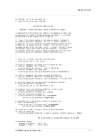
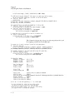
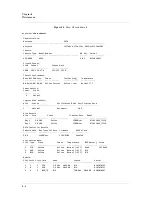
Management
Gateway
10.1.27.1
Power
Configuration
220
Private
IP
Subnet
169.254.6.0
Private
IP
Mask
255.255.255.0
Private
VLAN
1008
Private
Metalog
VLAN
1009
Chassis
GUID
3d17e8ce
‐
571e
‐
11dc
‐
9852
‐
ef323fbb290f
Switch
Password
#######
Switch
Master
Key
generate
Crypto
‐
officer
Username
admin
Crypto
‐
officer
Password
#######
Enter
'yes'
to
load
configuration
or
'r'
to
restart
#
yes
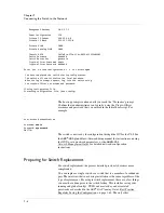
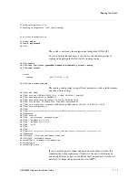
You
have
completed
the
switch
startup
configuration.
The
switch
will
now
initialize
the
local
database.
When
the
login
prompt
appears,
log
into
the
switch
using
the
crypto
‐
officer's
username
and
password.
Closing
configuration
file.
Processing
configuration
file.
(boot
‐
config)
...
The boot-up prompts continue until you reach the “Username” prompt.
Confirm that an administrator can log in by using the Crypto-Officer
username and password that you entered in the initial-boot script. For
example:
...
User
Access
Authentication
Username:
admin
Password:
mypassword
SWITCH>
The switch is now ready for configuration through the GUI or the CLI. See
the
ARX
®
GUI Quick Start: Network Setup
manual for instructions on using
the GUI to set up network parameters, or the
ARX® CLI
Network-Management Guide
for detailed network-configuration
instructions.
Preparing for Switch Replacement
For switch replacement, the process detailed previously becomes more
complicated.
You can replace a single switch or a switch that is a member of a redundant
pair. The interview that runs during installation is the same regardless of the
type of replacement. For a single switch replacement, there are a few things
you must have done prior to the switch failing. This includes saving your
running and global configs, UUID, and master key and associated
passwords as described in the
ARX
®
Site Planning Guide
, Best Practice:
Regularly Saving the Configuration, on page 1-62. The only other
Summary of Contents for ARX 6000
Page 1: ...ARX 6000 Hardware Installation Guide 810 0001 00 ...
Page 2: ......
Page 5: ...Table of Contents ...
Page 6: ......
Page 10: ...Table of Contents x ...
Page 12: ......
Page 22: ...Chapter 1 1 12 ...
Page 24: ......
Page 30: ......
Page 36: ...Chapter 3 Chassis Hardware 3 8 ...
Page 38: ......
Page 46: ......
Page 52: ......
Page 66: ......
Page 80: ......
Page 87: ...A Cable Connectors ARX 6000 Connectors Console Connector and Pinouts SFP Optical Connector ...
Page 88: ......
Page 92: ...Appendix A Cable Connectors A 6 ...
Page 94: ......
Page 100: ...Appendix B Removing and Replacing FRUs B 8 ...
Page 101: ...Index ...
Page 102: ......


