


LED Status Indicators
ARX
®
6000 Hardware Installation Guide
8 - 7
Ethernet-Port Link Status LEDs
MGMT Port on the SCM
The out-of-band management port on the System Control Module (SCM),
labeled “MGMT,” has two LEDs:
• Top – Link-status LED: steady green indicates that the port is enabled
and a link is established.
• Bottom – Activity LED: blinking green indicates packet traffic.
Link LED for Each NSM Port
Each client/server port on the Network Services Module (NSM) has
link-status LED labeled “Link.” This has the same function as the
Link-status LED on the MGMT port: steady green indicates that the port is
enabled and a link is established. There is no Activity LED for the
client/server ports.
The Link LED is over each Ethernet port in the NSM-TX, but it is
under
each Fibre port in the NSM-FX.
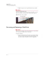
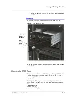
Disk Drive LEDs
The system disk drives provide three status LEDs:
• Red — indicates Activity
• Green — indicates Power
• Orange — indicates Failure
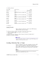
Fan Tray LEDs
The fan-tray module front panel provides two status LEDs, ALERT (top)
and STATUS (bottom). Table 8.2 describes the fan tray LED indicators and
associated conditions.
ALERT
STATUS
Condition
(Off)
Green
No failures.
(Off)
Yellow
Warning. This could indicate one of the following conditions:
•
Single-fan failure,
•
Temperature >50 degrees C, or
•
Temperature sensor open.
Contact F5 Support; you may need to replace the entire fan tray, as described in an
appendix of this manual.
Table 8.2
Fan Tray Status LEDs
Summary of Contents for ARX 6000
Page 1: ...ARX 6000 Hardware Installation Guide 810 0001 00 ...
Page 2: ......
Page 5: ...Table of Contents ...
Page 6: ......
Page 10: ...Table of Contents x ...
Page 12: ......
Page 22: ...Chapter 1 1 12 ...
Page 24: ......
Page 30: ......
Page 36: ...Chapter 3 Chassis Hardware 3 8 ...
Page 38: ......
Page 46: ......
Page 52: ......
Page 66: ......
Page 80: ......
Page 87: ...A Cable Connectors ARX 6000 Connectors Console Connector and Pinouts SFP Optical Connector ...
Page 88: ......
Page 92: ...Appendix A Cable Connectors A 6 ...
Page 94: ......
Page 100: ...Appendix B Removing and Replacing FRUs B 8 ...
Page 101: ...Index ...
Page 102: ......


