background image

Installing an IP Application Switch Using an Optional Rail-Mount Kit

Platform Guide: 8400 and 8800

A - 3

Attaching the inner rails and stops

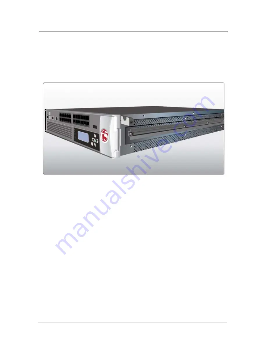
The first task in installing the optional rail-mount kit is to attach an inner rail 
and a stop to each side of the unit. Figure A.3 shows the unit with an inner 
rail and stop attached to one side.

Figure A.3  

An inner rail with stop installed

To attach the inner rails and stops to the unit

1. Attach an inner rail to each side of the unit, as shown in Figure A.3, 

using the four screws that you removed from each rack-mount ear.
Note that each side requires four screws.

2. Attach a stop to each side of the unit, near the front, as shown in 

Figure A.3, using the screws provided in the kit.

Attaching the outer rails

Once you have installed the inner rails and stops to the unit, you can attach 
the two outer rails to the rack. One outer rail is made specifically for the left 
side of the rack, while the other outer rail is made specifically for the right 
side of the rack.

Each outer rail includes a bracket on the front, with a square hole and a 
round hole. Figure A.4 shows a bracket with the square and the round holes.

Summary of Contents for 8400

Page 1: ...Platform Guide 8400 and 8800 MAN 0232 02 ...

Page 2: ......

Page 3: ...ng by F5 Export Regulation Notice This product may include cryptographic software Under the Export Administration Act the United States government may consider it a criminal offense to export this product from the United States RF Interference Warning This is a Class A product In a domestic environment this product may cause radio interference in which case the user may be required to take adequat...

Page 4: ...ii VCCI Class A Compliance This is a Class A product In a domestic environment this product may cause radio interference in which case the user may be required to take corrective actions ...

Page 5: ...Table of Contents ...

Page 6: ......

Page 7: ...lling the IP Application Switch hardware 2 2 Connecting the cables and other hardware 2 4 3 Operating the LCD Panel Introducing the LCD panel 3 1 Using the LCD panel 3 2 Pausing on a screen 3 2 Accessing LCD menus 3 2 Powering up the unit 3 2 Halting the unit 3 2 Powering down the unit 3 3 Rebooting the unit 3 3 Clearing alerts 3 3 Navigating through the LCD menus 3 4 Information menu 3 4 System m...

Page 8: ... 6 2 7 Understanding Platform Airflow Reviewing platform airflow information 7 1 Airflow for the 8400 8800 platform 7 1 8 Reviewing Hardware Specifications Reviewing hardware specifications 8 1 8400 specifications 8 2 8800 specifications 8 3 Additional acoustic airflow and altitude specifications 8 4 A Installing an IP Application Switch Using an Optional Rail Mount Kit Installing the optional rai...

Page 9: ...on Switch Platform Working with the IP Application Switch platform Getting started with the 8400 and 8800 platforms Familiarizing yourself with the IP Application Switch About this guide Finding help and technical support resources ...

Page 10: ......

Page 11: ...ever there are internal differences 8400 and 8800 platforms The 8400 and 8800 platforms Figure 1 1 support two 10 Gigabit XFPs twelve fiber small form factor pluggable SFP gigabit interface converters GBICs LC connector type and twelve copper 10 100 1000 interfaces WARNING Only optics modules provided by F5 Networks are supported in this platform For detailed specifications of each platform see Re...

Page 12: ... hardware For more information on mounting the hardware and attaching cables see Installing and connecting the hardware on page 2 1 The IP Application Switch comes with the hardware that you need for installation However you must also provide standard peripheral hardware such as a serial terminal if you want to administer the IP Application Switch directly Components provided with the IP Applicati...

Page 13: ...witches or concentrators to connect to the IP Application Switch network interfaces The devices you select must be compatible with the network interface cards installed in the IP Application Switch The devices can support 10 100 Ethernet or Gigabit Ethernet Ethernet requires either a 10 Mbps or 100 Mbps hub or switch Gigabit Ethernet requires a compatible Gigabit Ethernet switch You can use a USB ...

Page 14: ... unit You can also view the indicator lights for hard disk access The interfaces on every IP Application Switch are labeled so it should be clear what each port is no matter which hardware configuration you have purchased Note that the USB port number 7 in Figure 1 3 is oriented so that you can plug the cable in with the correct side up Previous platforms required you to plug the cable in upside d...

Page 15: ...Platform Guide 8400 and 8800 1 5 Figure 1 4 following illustrates the back of a IP Application Switch Note that all ports are labeled Figure 1 4 Back view of the IP Application Switch with power input panel 1 Power supply 1 2 Power supply 2 optional ...

Page 16: ...ior on page 4 1 Replacing a fan tray and filter You can learn how to replace a fan tray and filter For more information see Changing the fan tray and filter on page 5 1 Changing a power supply You can learn how to replace a power supply For more information see Changing a power supply on page 5 3 Replacing the drive tray You can learn how to replace the tray that contains the drives for the system...

Page 17: ...grades for BIG IP Systems This guide provides detailed information about installing upgrades to the BIG IP system It also provides information about licensing the BIG IP system software and connecting the system to a management workstation or network Configuration Guide for BIG IP Local Traffic Management This guide contains any information you need for configuring the BIG IP system to manage loca...

Page 18: ...ts names and commands We apply bold text to a variety of items to help you easily pick them out of a block of text These items include web addresses IP addresses utility names and portions of commands such as variables and keywords For example with the bigpipe pool pool_name show command you can specify a specific pool to show by specifying a pool name for the pool_name variable Identifying refere...

Page 19: ...ins additional special conventions used in command line syntax Item in text Description Indicates that the command continues on the following line and that users should type the entire command without typing a line break Identifies a user defined parameter For example if the command has your name type in your name but do not include the angle brackets Separates parts of a command Indicates that sy...

Page 20: ...tility The Welcome screen in the Configuration utility contains links to many useful web sites and resources including The F5 Networks Technical Support web site The F5 Solution Center The F5 DevCentral web site Plug ins SNMP MIBs and SSH clients F5 Networks Technical Support web site The F5 Networks Technical Support web site https support f5 com provides the latest documentation for the product ...

Page 21: ...2 Installing the IP Application Switch Platform Installing and connecting the hardware ...

Page 22: ......

Page 23: ...mount using the optional rail mount kit you need to perform two preliminary steps First you must remove the standard mount related hardware known as rack mount ears from the unit because the mount hardware is no longer necessary Second you must install the optional rail mount kit Once you have completed these tasks you can then install the unit into the rack and connect the cables and other hardwa...

Page 24: ... rail mount kit to hold the unit use the procedures described in Appendix A Installing an IP Application Switch Using an Optional Rail Mount Kit The appendix describes how to perform the two preliminary tasks of removing the standard mount hardware from the unit and adding the rail hardware to the unit and the rack The appendix also describes how to install the unit into the rack A shelf or simila...

Page 25: ...00 and 8800 2 3 Figure 2 1 shows the orientation of the IP Application Switch and the mounting screws for installation in a standard 19 rack Figure 2 2 following shows the IP Application Switch installed in the rack Figure 2 1 Platform orientation for rack mounting ...

Page 26: ...orm these tasks use the following procedure Note that you use this procedure regardless of the type of mount you installed front mount or rail mount To connect the cables and hardware for input output 1 Connect the hardware that you have chosen to use for input output For details about connecting the system to a management workstation or network see Chapter 2 Connecting a Management Workstation or...

Page 27: ...t on each unit number 3 in Figure 1 3 on page 1 4 3 Connect the power cable to the power input panel number 2 in Figure 1 4 on page 1 5 and then connect it to the power source If the system has the DC power option a readily accessible disconnect must be incorporated in the wiring for the installation 4 Turn on the unit and begin licensing the system For details about licensing the BIG IP system se...

Page 28: ...Chapter 2 2 6 ...

Page 29: ...3 Operating the LCD Panel Introducing the LCD panel Using the LCD panel Navigating through the LCD menus ...

Page 30: ......

Page 31: ...find information about using the LCD and its functionality System menu Use the System menu to reboot netboot or halt the unit This menu also has options for setting the properties of the management interface MGMT and the serial port Screens menu Use the Screens menu to set up the informational screens you would like the LCD to cycle through The information screens include system status statistics ...

Page 32: ... screen displayed on the LCD every 4 seconds Accessing LCD menus Press the X button to put the LCD panel in Menu mode so you can access the menus The buttons Left Arrow Right Arrow Up Arrow and Down Arrow are only functional when the LCD is in Menu mode For more information about using the LCD menus see Navigating through the LCD menus on page 3 4 Powering up the unit When you want to power up a u...

Page 33: ...e is off Simply pressing the green Check button again powers the unit back on The system is designed to remember the state of the chassis soft power state even when the AC power is removed and to restore that state when AC power is reapplied If you power off the chassis using the Check button and then disconnect the power cord the power state of the chassis returns to the soft powered off state wh...

Page 34: ...ctionality You can also find more information on what different LED activity means and the failover state of the unit in a redundant system The following table Table 3 1 shows the options available on the Information menu Option Description How to use the LCD Displays a vertical scrolling text description on how to use the LCD panel Front Panel LEDs Displays a vertical scrolling text description o...

Page 35: ...tboot Select this option if you are installing software from a PXE server IP address Type the management interface IP address You can use only an IPv4 address Netmask Set the netmask for the management interface IP address Default route Type in the default route for the management interface This route is necessary if you plan to manage the unit from a different subnetwork Commit Select this option...

Page 36: ... InfoScreen Information screen Displays the information screen menu DateScreen Date and Time screen Displays the date and time MACscreen MAC addresses screen Displays the MAC addresses on the unit SysinfoScreen System information screen Displays system information TMMCPUScreen CPU usage Displays the CPU usage percentage TMMMemoryScreen Memory usage Displays the memory usage TMMAuthScreen Auth requ...

Page 37: ...at displayed on the LCD screen This heartbeat displays if the SCCP is running on the system This heartbeat does not affect the failover mechanism of the system Contrast Use the Left and Right arrow keys on the LCD to set the contrast of the LCD On Brightness This setting provides the ability to adjust the LCD backlight brightness Off Brightness This setting controls the brightness of the LCD panel...

Page 38: ...Chapter 3 3 8 ...

Page 39: ...4 Using Additional IP Application Switch Functionality Understanding LED behavior Working with interfaces Hardware acceleration ...

Page 40: ......

Page 41: ...Description Power Reports the power status on green present yellow or off none Note that units with the capacity for additional power supplies have a Power LED for each power supply bay Status Reports the state of the system Active standalone Green or Standby Yellow Activity Reports storage device and network device activity Alarm Reports a non specific alert level Use SNMP traps system logs or th...

Page 42: ...esponding LED behavior Table 4 4 Indicator LED functions Configuring indicator LEDs to display node status Alerts that cause the indicators to change are defined in the etc alertd alert conf and config user_alert conf files on the BIG IP system You should only edit config user_alert conf to add new alerts The etc alertd alert conf defines standard system alerts System State Alarm LED Activity LED ...

Page 43: ... the etc alertd alert conf Yellow intermittent Activity indicator LED A yellow intermittent Activity LED indicates that host traffic is present Also while the kernel is loading the Activity indicator LED flashes yellow intermittently when the disk is accessed This condition is normal and occurs only during boot up alert BIGIP_MCPD_MCPDERR_POOL_MEMBER_MON_DOWN Pool member monitor status down snmptr...

Page 44: ...er green even though there is no external client server traffic Green solid Activity indicator LED When an 8400 platform shows a solid green Activity LED during normal operations it indicates that the platform is operating outside of expected behaviors and could be considered abnormal Contact technical support for assistance Green or yellow solid Status indicator LED When the Status indicator LED ...

Page 45: ...e If you try to use interfaces with the same number the SFP interface overrides the RJ45 interface however you can use software settings to override the hardware default The SFPs can only work a 1000 Mbit Displaying status and settings for interfaces From the command line interface use the following syntax to display the current status and the settings for all installed interfaces b interface show...

Page 46: ... attempting to auto negotiate interface settings with an interface that has the speed and duplex settings forced you will experience severe performance degradation Use the following syntax to set the media type b interface if name list media media type auto The valid media types for this command are 10baseT duplex 100baseTX duplex 1000baseT duplex 1000baseSX full 1000baseLX full 10GbaseSR full 10G...

Page 47: ...plex setting is not saved to config bigip_base conf Use the following syntax to set the duplex mode b interface if_name duplex full half Hardware acceleration The Packet Velocity ASIC 10 optimizes application performance and reduces application wait times An ASIC is an Application Specific Integrated Circuit The Packet Velocity ASIC is designed to accelerate Layer 4 decisions Off loading the Layer...

Page 48: ...Chapter 4 4 8 ...

Page 49: ...5 Maintaining the IP Application Switch Platform Reviewing maintenance options and operations Changing the fan tray and filter Changing a power supply Changing the drive tray ...

Page 50: ......

Page 51: ...time the fans will wear out requiring you to replace the fan tray Note We recommend that you inspect the fan tray and filter every four months Replace the fan tray if any of the fans are not functional Replace the filter when you replace the fan tray Replacing the fan tray and filter You do not need special tools to replace the fan tray and filter You can perform this maintenance while the unit is...

Page 52: ... 5 1 shows an example of the fan and filter tray assembly partially removed from the BIG IP system You can also replace the filter without replacing the fan tray This requires you to remove the fan tray and take out the old filter and insert a new one To replace the filter only 1 Start by opening the front panel of the BIG IP unit running in standby mode 2 The fan tray is held on the chassis by a ...

Page 53: ...it and powering the system off After you install the power supply in the standby system force the active system to fail over and install the power supply replacement in the other unit of the redundant system To halt and power off the unit 1 On the LCD panel press the X button then use the arrow keys to navigate to the System menu 2 Press the Check button 3 Navigate to the Halt menu 4 Press the Che...

Page 54: ...connected to the system when you slide it completely into the chassis 5 Tighten the knurled fasteners into place by turning them clockwise 6 Close the front panel of the unit Figure 5 2 The power supply Figure 5 2 shows an example of the power supply partially removed from the BIG IP system ...

Page 55: ... power up the system and force the active system to fail over Install the drive tray replacement in the other unit of the redundant system You must halt the system and shut it down before you replace the drive tray To halt and power off the unit 1 On the LCD panel press the X button then use the arrow keys to navigate to the System menu 2 Press the Check button 3 Navigate to the Halt menu 4 Press ...

Page 56: ...the knurled fasteners into place by turning them clockwise 6 Close the front panel of the unit Figure 5 3 The removable drive tray Figure 5 3 shows an example of the drive tray assembly partially removed from the BIG IP system ...

Page 57: ...6 Working with Environmental Guidelines for the IP Application Switch Platform Environmental requirements ...

Page 58: ......

Page 59: ...ions Install the rack according to the manufacturer s instructions and check the rack for stability before placing equipment in it Build and position the rack so that once you install the IP Application Switch the power supply and the vents on both the left and right sides of the unit remain unobstructed The IP Application Switch must have adequate ventilation around the unit at all times Do not a...

Page 60: ...owered installation must meet the following requirements Install the unit using a 20 Amp external branch circuit protection device For permanently connected equipment incorporate a readily accessible disconnect in the fixed wiring Use only copper conductors ...

Page 61: ...7 Understanding Platform Airflow Reviewing platform airflow information ...

Page 62: ......

Page 63: ...ant to understand the unit s airflow direction so that you can ensure proper cooling Airflow for the 8400 8800 platform The 8400 8800 platform employs a positive pressure fan system which blows cold air in from the right side of the chassis and exhausts hot air out the left and back sides of the chassis as shown in Figure 7 1 Figure 7 1 Airflow in 8400 8800 platform ...

Page 64: ...Chapter 7 7 2 ...

Page 65: ...8 Reviewing Hardware Specifications Reviewing hardware specifications 8400 specifications 8800 specifications Additional acoustic airflow and altitude specifications ...

Page 66: ......

Page 67: ...NMP gets and traps iControl API using CORBA SOAP XML Dynamic Content Support ASP active server pages VB visual basic script ActiveX JAVA VRML CGI Cool Talk Net Meeting Real Audio Real Video Netshow Quick Time PointCast any HTTP encapsulated data Device Redundancy Watchdog timer fail safe cable primary secondary Web Server Application Compatibility Any IP based web or application server Routing Pro...

Page 68: ...wer Supply Optional redundant power supply ASIC Packet Velocity ASIC 10 PVA 10 Network Interfaces 12x10 100 1000 Copper ports 12x1000Base X SFP Fiber ports 1000BASE SX 850nm LC Connector 6 modules included 1000BASE LX 1310nm LC Connector optional 2x10 Gigabit XFP ports 10GBASE SR 850nm LC Connector optional 1x10 100 Ethernet Management port Hard Drive Capacity 512 MB flash with 80 Gigabyte hard dr...

Page 69: ...sor Two Dual Core Opteron 2 6 GHz ASIC Packet Velocity ASIC 10 PVA 10 Network Interfaces 12x10 100 1000 Copper ports 12x1000Base X SFP Fiber ports 1000BASE SX 850nm LC Connector 6 modules included 1000BASE LX 1310nm LC Connector optional 2x10 Gigabit XFP ports 10GBASE SR 850nm LC Connector optional 1x10 100 Ethernet Management port Hard Drive Capacity 512 MB flash with 80 Gigabyte hard drive RAM 2...

Page 70: ...its 1 All measurements taken at 1 meter A weighting 2 Per BELCORE GR 63 CORE section 4 1 3 60 meters 197 feet below sea level to 1800 meters 5905 feet above sea level Detail Units 8400 and 8800 Acoustic 1 Front face db 65 Left face db 64 Right face db 68 Rear face db 65 Altitude 2 Operational Feet 5905 Non operational Feet 40000 Airflow Entire chassis cfm 128 1 Table 8 4 Acoustic altitude and airf...

Page 71: ...A Installing an IP Application Switch Using an Optional Rail Mount Kit Installing the optional rail mount kit ...

Page 72: ......

Page 73: ...nd install the unit into the rack you need to perform the following tasks Remove some standard mount hardware from the unit Install the rail mount kit hardware Install the unit into the rack Connect cables and other hardware To perform these tasks follow the instructions in the following sections Removing standard mount hardware from the unit The first step in installing a rail mount kit is to rem...

Page 74: ... screws you removed for the next procedure Installing the kit hardware After you have removed the rack mount ears from the unit you must install the rail mount kit The rail mount kit consists of these parts Two inner rails that you attach to either side of the unit Once the kit is installed these inner rails slide into the outer rails that you install onto the rack Two stops that you attach to eit...

Page 75: ...it as shown in Figure A 3 using the four screws that you removed from each rack mount ear Note that each side requires four screws 2 Attach a stop to each side of the unit near the front as shown in Figure A 3 using the screws provided in the kit Attaching the outer rails Once you have installed the inner rails and stops to the unit you can attach the two outer rails to the rack One outer rail is ...

Page 76: ... corresponds to the side of the rack onto which you are installing the rail 2 Attach the outer rail and bracket onto the rack as shown in Figure A 5 Note the following a If the rack is a round holed rack use standard rack screws b If the rack is a square holed rack hang one of the separate brackets provided with the kit onto each end of an outer rail and then use the screws provided to attach each...

Page 77: ... following procedure to install the unit into the rail mount rack To install the unit into the rack 1 Slide the unit into the rack fitting the inner rails of the unit to the outer rails of the rack 2 On each side of the unit screw a nut into the stop that you installed on the unit Connecting cables and other hardware After you have installed the unit into the rack you need to connect certain cable...

Page 78: ...Appendix A A 6 ...

Page 79: ...B Platform Specific Hazardous Substance Levels for China 8400 platform 8800 platform ...

Page 80: ......

Page 81: ...azardous Substance Levels for China Platform Guide 8400 and 8800 B 1 8400 platform This table lists hazardous substances controlled by China and shows how the F5 Networks 8400 platform components conform to the standards ...

Page 82: ...Appendix B B 2 8800 platform This table lists hazardous substances controlled by China and shows how the F5 Networks 8800 platform components conform to the standards ...

Page 83: ...Glossary ...

Page 84: ......

Page 85: ...e it connects to the network DNS DNS stands for Domain Name System It is a service that translates domain names into IP addresses For example the domain name www siterequest com might translate to 101 102 103 104 FRU An FRU is a field replaceable unit You can order FRUs to replace certain parts of the unit including the fan tray fan filter drive tray and power supply LCD LCD stands for liquid crys...

Page 86: ...n SSL connection start with HTTPS instead of HTTP subnetwork The portion of a network that shares a common address component For instance on TCP IP networks a subnetwork is all devices whose IP addresses have the same prefix segment Telnet Telnet is a terminal emulation program for TCP IP networks Telnet runs on your computer and connects it to a server on the network It then allows you to enter c...

Page 87: ...Index ...

Page 88: ......

Page 89: ... online help 1 10 about the Welcome screen 1 10 Configuration Worksheet 1 7 cooling system for platform 7 1 copper interfaces 1 1 D DC power 2 2 2 5 DC powered equipment guidelines 6 2 drive tray replacement 5 5 duplex mode 4 6 E electrostatic discharge ESD 2 2 6 1 environmental guidelines 6 1 See also hazardous substance restrictions Ethernet hub requirements 1 3 F fail over cable 1 2 2 5 fan sys...

Page 90: ...ing 4 6 Menu mode 3 2 3 4 menus on LCD panel 3 4 N Network and System Management Guide 1 7 new terms identifying 1 8 O online help 1 10 optic modules 8 2 8 3 Options menu 3 1 3 7 P Packet Velocity ASIC 10 4 7 panel See LCD panel platform cooling system 7 1 platform airflow for 8400 8800 platform 7 1 See also airflow platform orientation 2 3 ports 1 4 1 5 positive pressure fan system 7 1 power cabl...

Page 91: ...acks A 3 standard operating state See indicator LED Status LED 4 1 when solid green 4 4 when solid yellow 4 4 stylistic conventions 1 8 switches 1 3 syntax See command syntax identifying system airflow See airflow System menu 3 1 3 5 T technical documentation finding 1 10 technical support web site 1 10 U USB port and supported CD drives 1 3 V ventilation 6 1 7 1 W warnings environmental 6 1 See a...

Reviews: