


XTP T USW 103 Switcher • XTP System Configuration Software
36
Add an EDID File to the EDID Library
1.
In the
Available EDID
panel, click the
Add EDID to Library
button (see
8
on the previous page). The
Browse
window opens.
2.
Navigate to and select the desired EDID file and click
Open
. The EDID file appears in the
Available EDID
panel (see
4
on the previous page).
3.
Assign the EDID file from the
Available EDID
panel to import the EDID to the device.
Save output EDID
1.
On the
EDID Minder
screen, right-click on the desired EDID setting in the
Connected
Outputs
panel (see
3
on the previous page).
2.
Select the
Save EDID to Library
option. The EDID setting is saved to the connected
PC. Alternatively, right-click on the desired EDID, select
Copy
, and then
Paste
the EDID
into the
Favorites
or
Available EDID
panel.
Set favorite EDID
To add commonly used EDID settings to the
Favorites
panel for quick access, perform
one of the following methods:
•
Click and drag the desired EDID from the
Connected Outputs
or the
Available EDID
panel to the
Favorites
panel. The EDID setting is copied to the
Favorites
panel (see
2
on the previous page).
•
Right-click the desired EDID and select
Copy
. Then,
Paste
the EDID setting into the
Favorites
panel.
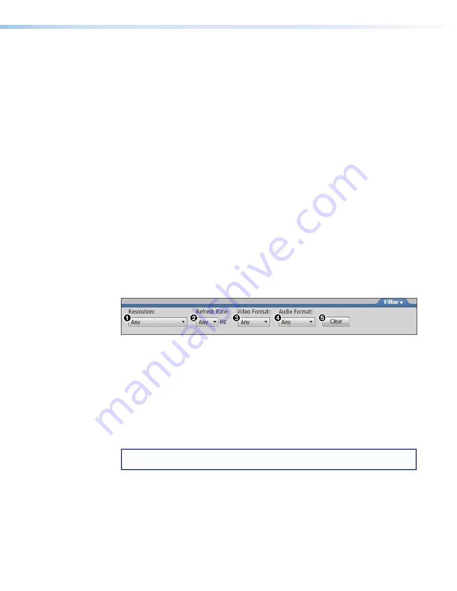
EDID filters
The filters (see figure 31) can be used to easily locate a specific EDID setting.
1
Resolution filter
2
Refresh Rate filter
3
Video Format filter
4
Audio Format filter
5
Clear button
Figure 31.
EDID Minder Filters
To use a filter or combination of filters, perform the following:
1.
Select an EDID setting from one of the drop-down lists of the associated filter (see
figure 31,
1
-
4
). The available EDID options that match the filter selection are
displayed in their respective panels.
2.
Repeat step 1 to apply more filters.
NOTE:
To clear the currently applied filters, click the
Clear
button next to the filters (see
figure 31,
5
). All filters are reset.
Common timings
This function automatically displays available EDID settings that are common among
multiple selected outputs.
1.
Hold <Ctrl> and click the desired outputs in the
Connected Outputs
panel. The
Common Timings
tab (located to the right of the
Connected Outputs
panel) appears,
listing the EDID settings common among the selected outputs.
2.
Select the desired common EDID. The EDID is shown in the
Available EDID
panel.
Summary of Contents for XTP T USW 103
Page 6: ......


