6
TLC Pro 526M, 726M, and 1026M Series • Setup Guide (Continued)
Contact closure
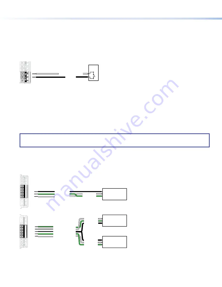
The contact closure port is used to monitor switches, sensors, or similar devices and trigger events in response to changes to the
monitored device. Insert the wires from the monitored device into the contact closure port.
A 1k ohm pull-up resistor in a TTL (5 VDC) circuit senses the contact closure.
•
When the external switch closes (shorts to ground, logic low) the port is on.
•
When the external switch opens (logic high) the port is off.
Connect two wires to the contact closure port, as shown in figure 10. If both the IR port and contact closure port are used, the
ground pin must be shared by both devices.
SG
IN
IR/C IN
Ground
Contact Closure Input
Switch,
Sensor
Figure 10.
Contact Closure Port
COM ports
The TLC Pro Control System has two COM ports, which support software flow control. They share a common ground pin. COM
ports control and receive status messages from connected devices, using the following RS-232 protocols:
•
300 to 115200 baud (default = 9600 baud)
•
7 or 8 data bits (default = 8)
•
1 or 2 stop bits (default = 1)
•
No parity, even parity, or odd parity (default = no parity)
•
This port supports flow control. The default is no flow control.
NOTE:
The maximum distance from the touchpanel to the device being controlled is usually 200 feet (61 m), but this can vary,
depending on factors such as cable gauge, baud rates, environment, and output levels from the touchpanel and the device
being controlled.
To wire the ports, see figure 11. If single port is used, it can be wired using either COM 1 or COM 2. (Figure 11 shows COM 1.)
For bidirectional serial communication, the transmit, ground, and receive pins must be wired at both the adapter and the device
being controlled. For information about wiring the device being controlled, see the user guide for that device.
If you use cable that has drain wire, the drain wire must be tied to ground at both ends. For best results, insulate the common or
drain wires using heat shrink.
Receive (Rx)
Transmit (Tx)
Transmit
COM 1 Rx
Receive
COM 1 Tx
G
Ground
1
Tx
Rx
Rx
G
Tx
COM1
RELA
YS
COM2
1
RELA
Y
S
IN
Tx
Rx
Rx
G
Tx
IR/C IN
COM1
COM2
IN
IR/C
IN
Transmit
COM 2 Rx
Receive
COM 2 Tx
Ground
Receive (Rx)
Transmit (Tx)
Ground
Device
controlled by
RS-232
Receive (Rx)
Transmit (Tx)
Transmit
Rx
Receive
Tx
G
Ground
Device 2
controlled by
RS-232
Device 1
controlled by
RS-232
Wiring a single COM port
Wiring both COM ports
Figure 11.
COM Ports


