background image

Using the Command and Response Tables

The command and response tables on the following pages 
list valid command ASCII codes, the SCP responses to the host, 
and a description of the command function or the results of 
executing the command.
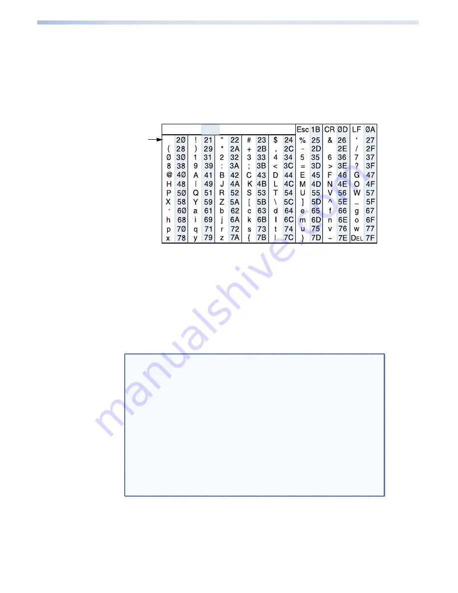
The ASCII to hexadecimal conversion table below is for use with 
the command and response tables.

ASCII to Hex  Conversion Table

Space

Symbol Definitions

]

  =  CR/LF (carriage return/line feed) (hex 0D 0A)

}

  =  Soft carriage return (no line feed)

E

  =  Escape key

  •  =  Space

X!

  =  Firmware number

NOTES:


 Unless otherwise indicated, commands are not case 

sensitive.

• 

Although most of the ASCII commands are not case  
sensitive, each uppercase and lowercase letter has 
its own hex code. For example, the hex equivalent 
for uppercase Q is 51; the code for lowercase 
q is 71. The hex codes for both versions of the 
same letter can be used interchangeably unless 
otherwise stated.
In the SIS command and response tables, only the 
lowercase version of the command and its hex 
equivalent are shown. 

33

SCP 104 and SCP 226 • Remote Communication

Summary of Contents for SCP 104 AAP

Page 1: ...68 959 01 Rev F 07 12 System Control Panels SCP 226 and SCP 104 Series User Guide ...

Page 2: ...glich ist oder aus der Wandsteckdose ziehen Schutz des Netzkabels Netzkabel sollten stets so verlegt werden daß sie nicht im Weg liegen und niemand darauf treten kann oder Objekte darauf oder unmittelbar dagegengestellt werden können Wartung Alle Wartungsmaßnahmen sollten nur von qualifiziertem Servicepersonal durchgeführt werden Die internen Komponenten des Gerätes sind wartungsfrei Zur Vermeidun...

Page 3: ...l device pursuant to part 15 of the FCC rules The Class A limits provide reasonable protection against harmful interference when the equipment is operated in a commercial environment This equipment generates uses and can radiate radio frequency energy and if not installed and used in accordance with the instruction manual may cause harmful interference to radio communications Operation of this equ...

Page 4: ...ential to result in death or severe injury ATTENTION Attention indicates a situation that may damage or destroy the product or associated equipment NOTE A note draws attention to important information Copyright 2012 Extron Electronics All rights reserved Trademarks All trademarks mentioned in this guide are the properties of their respective owners ...

Page 5: ...the Firmware Loader Program 27 Loading Firmware to the SCP 28 Remote Communication 31 Setting Up RS 232 Communication 31 Communications Between the Host and the SCP 31 SCP initiated Messages 32 Error Responses 32 Using SIS Commands 32 Using the Command and Response Tables 33 Symbol Definitions 33 Command and Response Table for SIS Commands 34 Special Function SIS Commands 37 Command and Response T...

Page 6: ...SCP 104 and SCP 226 Contents vi ...

Page 7: ...te all of the MLC 104 and 226 models and most of the System 5 IP front panel controls The SCP provides an economical means of controlling devices from multiple locations in a room For example a presenter could have control from a lectern at the front of the room while at the same time another person is able to control the same devices from the back of the room The SCP panels have bidirectional com...

Page 8: ...easily identified even in low light Their labels can be removed and replaced to reflect the assigned button functions if desired System expanding SCP 226 only The SCP 226 panels can be daisy chained with Extron control modules IRCMs and RCMs and an IR Link to provide versatile remote control options Furniture and wall mounting The SCPs can be mounted to walls or furniture using optional wall boxes...

Page 9: ...ED LOCAL MONITO R OUTPU T INPUT H SHIFT RGB 109 xi VGA INTERF ACE W ADSP ID PIN 4 ID PIN 11 DISP LAY 1 2 3 4 5 6 VOL UME IR PC AUX VIDE O DVD VCR DOC CAM LAPT OP AUT O IMAG E ON OFF DVD VCR CON TRO L PLAY NEXT FWD PAUS E STOP TUNE R Tx PREV REW TITLE MENU ENTE R DVD VCR SCP 226 SCRE EN UP SCRE EN DOW N TCP IP TouchLink Control System GlobalViewer A V Resource Management and Remote Control Applicat...

Page 10: ...SCP 104 IP VOLUME 1 2 3 4 ON OFF VID EO AUX VID EO PC IM AGE MUTE VID EO AUX VID EO PC IM AGE MUTE Extron MLC 104 IP MediaLink Controller Extron SCP 104 System Control Panel Extron MLS 103V MediaLink Switcher Projector Video Video Audio Audio Video RS 232 or IR Projector Control RS 232 Switcher Control Extron SI 26 Surface Mount Speakers Extron MPA 152 Mini Power Amplifier DVD VCR Figure 2 Connect...

Page 11: ... operation of the SCP 104 226 into a wall or furniture Do not use the SCP near water or expose it to liquids WARNING Risk of fire or electric shock Do not expose this apparatus to rain or moisture Clean the SCP only with a dry cloth Do not install the SCP near any heat source such as a radiator heat register stove or other apparatus that produces heat including amplifiers Unplug the SCP during lig...

Page 12: ... 5 IP plug a 12 VDC power supply into slots A and B of either of the IRCM RCM or SCP captive screw connectors 6 Restore power to all equipment Installing or Replacing Button Labels By default the SCP button caps are prelabeled for your convenience However they can be customized The button assembly consists of a clear lens cap the button label and a white diffuser see figure 3 on the next page To r...

Page 13: ...the label sheets included with the SCP Remove the label from the backing and if applicable peel the protective film from the front of the label NOTE If desired you can create customized labels using a label maker such as the Brother P touch and clear label material Cut the labels so that they are square and measure inch on each edge 6 Insert the new label into the clear button cap aligning the whi...

Page 14: ...ress DIP switches Set these DIP switches as appropriate for your system configuration Switch 1 Switches the SCP between connected and standalone modes Set this switch as follows Off down if the SCP will be connected to an MLC or a System 5 IP On up if the SCP will be operating in standalone mode not connected to a controller 1 ON 2 3 4 SCP 104 and SCP 226 Installation and Operation 8 ...

Page 15: ...ese connectors On an SCP 226 you can connect an MLC or System 5 IP to one connector and an IR Link another SCP or a control module such as an IRCM to the other connector The SCP can receive power from the MLC or System 5 IP through pins A and B of either of these connectors Wire the connectors as shown in Connecting to the MLC 104 226 the System 5 IP and Control Modules on page 13 c IRCM RCM conne...

Page 16: ...ity 8 data bits no flow control Use a female 9 pin to bare wire RS 232 cable or a universal control cable UC50 or UC100 to connect a your computer or control system to the SCP as follows 1 Wire the unterminated end of the RS 232 cable to the provided 3 pole captive screw plug as follows Connect the transmit wire to pin 1 which plugs into the transmit Tx port Connect the receive wire to pin 2 which...

Page 17: ...G 5 Rx G Figure 7 Connecting a Host to the SCP 226 2 Plug the 3 pole connector into the RS 232 port on the SCP rear panel NOTES DIP switch 1 must be set to On up for the SCP to be able to communicate with the computer or terminal emulator Do not connect anything to this port if an MLC or a System 5 IP is connected to the SCP SCP 104 and SCP 226 Installation and Operation 11 ...

Page 18: ...nnecting the Power Supply WARNING Risk of electric shock The two power cord wires must be kept separate while the power supply is plugged in Remove power before continuing To verify the polarity before connection plug in the power supply with no load and check the output with a voltmeter ATTENTION When you are connecting the power supply voltage polarity is extremely important Applying power with ...

Page 19: ... 2 01 or higher The diagrams in this section are guides the SCPs control modules and IR Link can be daisy chained in other combinations as well SCP 104 to MLC 104 IP Plus SCP 104 200 61 m max to Last Device E B A SCP Communication 12 VDC Ground Drain Wire MLC 104 IP Plus Rear Panel Extron CTLP Cable Color Code Ground Drain Wire E D C B A SCP Communication Modulated IR for IR Link Control Module Co...

Page 20: ...61 m max to Last Device IRCM DV Control Module Address 1 and 2 IRCM DV Control Module Address 3 and 4 E B A SCP Communication 12 VDC Ground Drain Wire Ground Drain Wire E D C B A SCP Communication Modulated IR for IR Link Control Module Communication 12 VDC White Black Drain Wire Violet Red C E B A MLC 104 IP Plus Rear Panel C IRCM RCM COMM LINK A B C D E V OUT GROUND CM IR IN SCP CONFIG DISPLAY V...

Page 21: ...t Red NOTE Maximum Two SCPs Per System MLC 226 IP Rear Panel C IRCM ACM RCM VOLUME SCP 226 IR DISPLAY Extron 1 2 3 4 5 6 ON OFF PIC MUTE AUTO IMAGE VCR DOC CAM PC LAPTOP DVD VOLUME SCP 226 IR DISPLAY Extron 1 2 3 4 5 6 ON OFF PIC MUTE AUTO IMAGE VCR DOC CAM PC LAPTOP DVD DVD VCR CONTROL PLAY NEXT FWD PAUSE STOP TUNER Tx PREV REW ENTER TITLE MENU TV VCR DVD VCR DVD VCR CONTROL PLAY NEXT FWD PAUSE S...

Page 22: ...ule Communication 12 VDC White Black Drain Wire Violet Red C B A NOTE Maximum Two SCPs Per System G V CM IRSCP E C B D A System Switcher Rear Panel DVD VCR CONTROL PLAY NEXT FWD PAUSE STOP TUNER Tx PREV REW ENTER TITLE MENU TV VCR DVD VCR CONFIG DISPLAY VOLUME SCP 104 ON PC DOC CAM VCR DVD OFF 1 2 3 4 NOTE DIP switch 4 must be in the On up position Figure 14 Connecting an SCP 104 to a System Switc...

Page 23: ...Green Black Drain Wire Violet Red NOTE Maximum Two SCPs Per System NOTE DIP switch 4 must be in the On up position VOLUME SCP 226 IR DISPLAY Extron 1 2 3 4 5 6 ON OFF PIC MUTE AUTO IMAGE PC VCR DVD LAPTOP DOC CAM G V CM IRSCP E C B D A System Switcher Rear Panel VOLUME SCP 226 IR DISPLAY Extron 1 2 3 4 5 6 ON OFF PIC MUTE AUTO IMAGE PC VCR DVD LAPTOP DOC CAM DVD VCR CONTROL PLAY NEXT FWD PAUSE STO...

Page 24: ...CLIP NORMAL VOLUME AUDIO ADJUST SIGNAL 2 3 4 5 PC PROJECTOR 1 INPUT SELECTION CONFIG IR Figure 16 Button Equivalents on an SCP 104 Connected to a System 5 IP Switcher SCP 226 System 5 IP Button 6 on the SCP is used for function button 4 on the System 5 IP VOLUME SCP 226 IR DISPLAY Extron 1 2 3 4 5 6 ON OFF PIC MUTE AUTO IMAGE PC VCR DVD LAPTOP DOC CAM SYSTEM 5 IP PC DOC CAM VCR PIC MUTE ON OFF MEN...

Page 25: ...ture you can use one of the following Extron mounting options or obtain an equivalent mounting option locally Follow the directions provided with the mounting option See the Accessories table for part numbers for these options External Wall Box EWB series Surface Mounting Box SMB Universal Controller Mount UCM MediaLink Mounting Wall Box MLM WB Mounting to an Electrical Box Follow these steps to m...

Page 26: ...P 226 L is designed to be mounted to a lectern To mount the SCP 226 L cut a hole of the required size see the templates in the Cutout Templates section beginning on page 47 for the dimensions and attach the SCP using the provided wood screws NOTE The templates are not to scale and are provided for reference only Extron SCP 226 L Lectern PROJE CTO R 1 2 3 4 5 6 VOLU ME CO NF IG IR PC AUX VID EO DVD...

Page 27: ...cted and the SCP buttons reflect the programming on the MLC Buttons that are not selected light dim amber On the System 5 IP only the buttons indicated by b in the following front panel illustrations and button 6 in group c can be programmed to light in the three colors See the Global Configurator help file for instructions on programming the buttons When a button is pressed or the knob is turned ...

Page 28: ...SCP 104 PROJECTOR VOLUME ON OFF 1 2 3 4 1 3 6 7 7 7 7 Figure 20 SCP 104 Front Panel SCP 104 AAP 4 3 6 1 7 7 7 7 Figure 21 SCP 104 AAP Front Panel SCP 104 and SCP 226 Installation and Operation 22 ...

Page 29: ...ure 23 SCP 226 AAP Front Panel VOLUME SCP 226 IR PROJECTOR Extron 1 2 3 4 5 6 ON OFF 1 3 2 6 7 7 7 7 5 Extron PROJECTOR 1 2 3 4 5 6 VOLUME IR ON OFF 1 3 6 2 4 5 SCP 226 AAP 7 7 7 7 7 7 SCP 104 and SCP 226 Installation and Operation 23 ...

Page 30: ...ions including input selection and room control for example raising stopping and lowering a screen or turning room lights on and off The SCP 104 models have four of these buttons while the SCP 226 models have nine The buttons indicated by b in the front panel illustrations have a different set of switch numbers from those indicated by c NOTE On the SCP 226 when it is connected to a System 5 IP the...

Page 31: ...ional Extron IR 402 remote control Point the remote directly at the sensor The remote has a range of approximately 30 feet 12 m within 40 degrees on either side of the axis Figure 25 shows use of the IR 402 with an SCP 226 L IR 402 Remote Extron PROJECTOR 1 2 3 4 5 6 VOLUME ON OFF SCP 226 SCP 226 L 40 40 30 feet maximum IR Figure 25 Using the IR 402 with an SCP 226 SCP 104 and SCP 226 Installation...

Page 32: ...ndicator LEDs g Faceplate attachment screws These four screws six on the SCP 226 AAP secure the faceplate to the SCP ATTENTION Do not remove these screws after the SCP has been installed in a wall or lectern Resetting To reset the SCP to the factory default version of the firmware press and hold the buttons numbered 1 and 3 on the front panel while applying power to the unit SCP 104 PROJECTOR VOLU...

Page 33: ... cabled to the RS 232 port on the SCP ATTENTION Do not attempt to upload firmware if an MLC or a System 5 IP is connected to the SCP The RS 232 cable from the PC must be connected directly to the SCP NOTE Each time that you replace the existing firmware the SCP is reset to the factory default settings Obtaining the Firmware Loader Program Use the Firmware Loader program to upload a new version of ...

Page 34: ...the SCP To update the firmware on your SCP 1 Visit the Extron website www extron com and click the Download tab 2 On the Download Center screen click Firmware on the left sidebar menu The Download Center Firmware screen appears 3 Locate SCP 104 226 on the firmware list and click on the Download link at right 4 Follow the instructions on the subsequent screens to download and install the latest fir...

Page 35: ...ice Name SCP 104 or SCP 226 Connection Method RS 232 Com Port Select the Com port through which your SCP will communicate with your PC via RS 232 Baud Rate 9600 10 Click Connect When the computer connects to the SCP the following message appears in the Connected Device field Figure 32 Successful Connection Message 11 In the New Firmware File Optional section of the Add Device screen click Browse S...

Page 36: ...n Firmware SCP_104_226 01 13 Click Add The Firmware Loader window opens with information about your selected firmware file displayed in the Devices field 14 Click Begin to start the firmware uploading process A prompt window opens advising you not to start any programs while the firmware is uploading Click OK to continue Figure 34 Firmware Loader Screen with Update Complete 15 When the firmware up...

Page 37: ...2 port shown at right For information on wiring this port see Wiring the RS 232 Port on page 10 Use the following protocol settings for your computer Baud rate 9600 Data bits 8 Parity None Stop Bits 1 Flow Control None NOTE For RS 232 communication DIP switch 1 must be set to On up Communications Between the Host and the SCP SIS commands consist of one or more characters per field No special chara...

Page 38: ...to execute the command because the command is invalid or contains invalid parameters the SCP returns an error response to the host Error response codes and their descriptions are shown below Each error response is followed by a carriage return E10 Invalid command E13 Invalid command parameter E23 Bad checksum E28 Bad filename File not found Using SIS Commands SIS commands can be used with the SCP ...

Page 39: ...e feed hex 0D 0A Soft carriage return no line feed E Escape key Space X Firmware number NOTES Unless otherwise indicated commands are not case sensitive Although most of the ASCII commands are not case sensitive each uppercase and lowercase letter has its own hex code For example the hex equivalent for uppercase Q is 51 the code for lowercase q is 71 The hex codes for both versions of the same let...

Page 40: ...on number format y yyy updated firmware version number format Example 0q 30 71 1 00 1 01 The factory version is 1 00 the updated version is 1 01 Query firmware version factory q or 1q 31 71 x xx Query firmware version updated 2q 32 71 y yy Query part number n 6E 60 671 nn or 60 672 nn 60 671 nn SCP 226 60 672 nn SCP 104 Query model name and description i 69 SCPnnn nnn 104 or 226 Command and Respon...

Page 41: ... 00 K2nn control module 2 address 01 K3nn control module 3 address 02 K4nn control module 4 address 03 nn indicates whether a connection is present or not present and the technology type 00 not present 01 present or IRCM VCR 02 IRCM DVD 03 IRCM DVD 06 RCM SC 07 RCM SCLT 08 IRCM Tape 09 CM 5BB 10 CM 20BB 11 IRCM DV 12 CM 9BLB 13 CM 3BLB 14 CM 19AC 99 Unrecognized Volume Relative Function Volume up ...

Page 42: ... Upload Go Upl When you receive the Go response upload the firmware according to the procedure for your terminal emulator When the upload is complete you receive the Upl response Reset to Default Settings Reset to factory defaults E zxxx 7A 78 78 78 ZapX Sets all button LEDs to amber 36 SCP 104 and SCP 226 Remote Communication ...

Page 43: ...ormed Y is the value for the button or switch and __ is the function number To view the setting of a function use __ where __ is the function number In the following tables the values of the function and variables are different for each command or function These values are given in the far right column 37 SCP 104 and SCP 226 Remote Communication ...

Page 44: ...lues Button release on front panel or remote control none SwRls X X the function switch number 128 options see the Switch and Button Table for the functions associated with the switches IRCM RCM Enablement Enable IRCM DV X Y 53 Rcm Y X X remote state 0 off 1 on Y remote address 0 IRCM 1 1 IRCM 2 2 IRCM 3 3 IRCM 4 Read RCM Y 53 Rcm Y X _ Indicates the On Off status of the selected remote control Co...

Page 45: ...unction 2 lights amber 5 function 3 4 slow blink green 6 input 1 5 slow blink red 7 input 2 6 slow blink amber 8 input 3 7 fast blink green 9 input 4 8 fast blink red 10 input 5 9 fast blink amber 11 input 6 Read FPC lamp Y 51 Lmp Y X _ Volume LED Control FPC volume LED control X Y 52 Vlmp Y X X LED blinking order 0 off 1 bottom 2 blink on 3 chase up 4 chase down Y LED selected 0 no LED 1 bottom L...

Page 46: ...ands on page 38 The Switch and Button table on page 44 shows which switch number is associated with each button or knob on the SCP control module or IR 402 In the Switch column locate the switch number displayed on your terminal emulator then look in the Button column beside the number to find out which button was pressed or released NOTES The SCP does not use all of the available buttons and swit...

Page 47: ... Extron 1 2 3 4 5 6 ON OFF 1 2 5 9 10 11 12 13 14 6 7 Figure 35 Switch Locations on the SCP 226 Fig_Switch locations SCP 104 SCP 104 PROJECTOR VOLUME ON OFF 1 9 10 11 12 2 Figure 36 Switch Locations on the SCP 104 41 SCP 104 and SCP 226 Remote Communication ...

Page 48: ...rol Control modules switch locations Each control module IRCM or RCM has 20 switches reserved for it no matter how many buttons are physically present on the module Module 1 switches 26 43 Module 2 switches 46 65 Module 3 switches 66 85 Module 4 switches 86 105 Switch numbers are sequential from left to right top row to bottom row as shown in figure 38 on the next page 42 SCP 104 and SCP 226 Remot...

Page 49: ... Button Switch Numbering Examples DVD Half Module 1 IRCM DV with DIP Switch Set for Addresses 0 and 1 Modules 1 and 2 RCM SC with DIP Switch Set for Address 2 Module 3 VCR Half Module 2 26 27 28 29 30 31 35 34 32 32 36 40 39 38 37 41 45 44 42 42 31 35 33 32 36 39 29 37 41 45 44 42 42 66 70 68 51 55 53 52 56 59 49 57 61 65 64 62 62 Module 3 has switches 66 to 85 Module 1 has switches 26 to 45 Modul...

Page 50: ...able Not available Not available Not available IR volume up IR volume down CM0_1 CM0_2 CM0_3 CM0_4 CM0_5 CM0_6 CM0_7 CM0_8 CM0_9 CM0_10 CM0_11 CM0_12 CM0_13 CM0_14 CM0_15 CM0_16 CM0_17 CM0_18 CM0_19 CM0_20 CM1_1 CM1_2 CM1_3 CM1_4 CM1_5 CM1_6 CM1_7 CM1_8 CM1_9 CM1_10 CM1_11 CM1_12 CM1_13 CM1_14 CM1_15 CM1_16 CM1_17 CM1_18 CM1_19 CM1_20 CM2_1 CM2_2 CM2_3 CM2_4 CM2_5 CM2_6 CM2_7 CM2_8 CM2_9 CM2_10 CM...

Page 51: ... Part Numbers SCP 104 black or white 60 672 02 03 SCP 104 AAP black 60 672 12 SCP 226 black or white 60 671 02 03 SCP 226 AAP black or white 60 671 12 13 SCP 226 L black or white 60 671 32 Included Parts These items are included in each order for an SCP 104 or SCP 226 Models Part Numbers 3 5 mm 5 pole male captive screw connector 2 100 460 01 3 5 mm 3 pole captive screw connector 100 459 01 ESD ca...

Page 52: ... MR 400 4 gang black or white 70 519 42 43 MR 500 5 gang black or white 70 519 52 53 External Wall Box EWB EWB 102 2 gang black or white 60 1162 02 03 EWB 103 3 gang black or white 60 1163 02 03 EWB 104 4 gang black or white 60 1164 02 03 EWB 105 5 gang black or white 60 1165 02 03 Surface Mounting Box SMB SMB 102 2 gang black 60 640 02 SMB 103 3 gang black 60 641 02 SMB 104 4 gang black 60 642 02...

Page 53: ...e templates are not to scale and are provided for reference only SCP 104 Cutout Template SCP 104 Cut Out Template for Extron s TEMPLATE IS NOT FULL SIZE 4 60 11 68 cm To install SCP 104 directly into furniture cut along this line Top Panel 2 83 7 40 cm 3 50 8 90 cm SURFACE CUT OUT AREA FOR FURNITURE MOUNT Location of SCP 104 4 50 11 43 cm 1 40 3 56 cm 0 61 1 55 cm 47 SCP 104 and SCP 226 Reference ...

Page 54: ...TE IS NOT FULL SIZE 4 50 11 43 cm To install SCP 104 directly into furniture cut along this line 8 33 21 16 cm 2 83 7 2 cm SURFACE CUT OUT AREA FOR FURNITURE MOUNT 7 26 18 44 cm Top Panel Location of SCP 104 1 45 3 68 cm 0 61 1 55 cm 48 SCP 104 and SCP 226 Reference Information ...

Page 55: ...long this line Top Panel 2 81 7 13 cm 5 24 13 3 cm SURFACE CUT OUT AREA FOR FURNITURE MOUNT Location of SCP 226 SCP 226 Cut Out Template for Extron s TEMPLATE IS NOT FULL SIZE 4 50 11 43 cm 6 40 16 3 cm 1 39 3 53 cm 0 61 1 55 cm 49 SCP 104 and SCP 226 Reference Information ...

Page 56: ...s TEMPLATE IS NOT FULL SIZE 4 50 11 43 cm To install SCP 226 directly into furniture cut along this line Top Panel Location of SCP 226 8 72 22 15 cm 2 81 7 13 cm SURFACE CUT OUTAREA FOR FURNITURE MOUNT 1 45 3 68 cm 0 61 1 55 cm 3 62 9 20 cm 50 SCP 104 and SCP 226 Reference Information ...

Page 57: ...51 cm TEMPLATE IS NOT FULL SIZE To install SCP 226 directly into furniture cut along this line Top Panel 3 15 8 00 cm Location of SCP 226 2 81 7 13 cm 5 24 13 30 cm SURFACE CUT OUT AREA FOR FURNITURE MOUNT 0 25 0 64 cm 0 30 0 76 cm 51 SCP 104 and SCP 226 Reference Information ...

Page 58: ...52 SCP 104 and SCP 226 Reference Information ...

Page 59: ...rates Dubai This Limited Warranty does not apply if the fault has been caused by misuse improper handling care electrical or mechanical abuse abnormal operating conditions or if modifications were made to the product that were not authorized by Extron NOTE If a product is defective please call Extron and ask for an application engineer to receive an RA return authorization number This will begin t...

Page 60: ...ron India 1800 3070 3777 Inside India Only 91 80 3055 3777 91 80 3055 3737 FAX Extron Japan 81 3 3511 7655 81 3 3511 7656 FAX Extron China 4000 EXTRON 4000 398766 Inside China Only 86 21 3760 1568 86 21 3760 1566 FAX Extron Asia 800 7339 8766 Inside Asia Only 65 6383 4400 65 6383 4664 FAX Extron Middle East 971 4 2991800 971 4 2991880 FAX Extron Korea 82 2 3444 1571 82 2 3444 1575 FAX 2012 Extron ...

Reviews: