
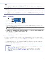

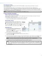

Stereo 8Ω or 4Ω Output Modes
Bridged Mono 8Ω/16Ω/70V/100V Modes
Stereo 8Ω or 4Ω
Speaker Loads
Wire output connector
to speaker loads as
shown to the right
1
2
CLASS 2 WIRING
OUTPUTS
BR
CH 2
CH 1
Mono 8Ω, 16Ω, 70V,
or 100V Speaker Loads
Wire output connector
to mono speaker load
as shown to the right
1
2
CLASS 2 WIRING
OUTPUTS
BR
CH 1
Figure 6.
Speaker Output Port and Wiring Diagram
ATTENTION:
•
You must use Class 2 wiring for this output to comply with UL requirements.
•
Vous devez utiliser le câblage de classe 2 pour cette sortie afin de vous conformer aux exigences UL.
•
Do not tie channel output pins to each other or to ground. Doing so will short out the outputs, damage the
amplifier, or both.
•
Ne pas lier les sorties 1 et 2 des canaux entre elles ou à la terre. Les sorties pourraient être court-circuitées et/
ou l’amplificateur pourrait être endommagé.
•
To avoid risk of damage to the amplifier or the speakers, always check that low-impedance speaker loads
(4 Ω/8 Ω/16 Ω) and high-impedance speaker loads (70 V/100 V) are appropriately wired to the amplifier for the
desired mode.
•
Pour éviter les risques de dommages à l’amplificateur ou aux haut-parleurs, vérifiez toujours que les charges de
haut-parleur à faible impédance (4 Ω/8 Ω/16 Ω) et les charges de haut-parleurs à haute impédance (70 V/100 V)
sont correctement câblées à l’amplificateur pour le mode souhaité..
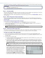
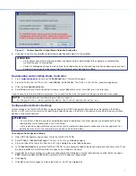
Step 5 — AT Port
Connect a RJ-45 connector to the AT port to connect and
communicate with the Dante network. It is also one of the
interfaces DSP Configurator uses to communicate with the
amplifier. The Link LED indicates when a connection is made.
Go to
Configure Dante Device Settings
on page 6 for
information on Dante settings. See the image to the right for
wiring.
Step 6 — Powering on Amplifier and Adjustments
Ensure all sources connected to the amplifier inputs are muted to
avoid potential speaker damage during power-up.
Reconnect all the power cables and switch on the rest of the
equipment before powering on the power amplifier. The amplifier
boots-up for up to 10 seconds as the front panel LED flashes
green.
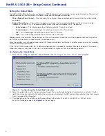
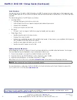
12345678
RJ-45
Connector
Insert Twisted
Pair Wires
Pins:
A cable that is wired as TIA/EIA T568A at one
end and T568B at the other (Tx and Rx pairs
reversed) is a "crossover" cable.
T568B
T568A
Crossover Cable
(for direct connection to a PC)
End 1
End 2
Pin Wire Color
Pin Wire Color
1
white-orange
1
white-green
2
orange
2
green
3
white-green
3
white-orange
4
blue
4
blue
5
white-blue
5
white-blue
6
green
6
orange
7
white-brown
7
white-brown
8
brown
8
brown
4
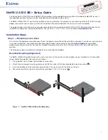
NetPA U 2002 SB • Setup Guide (Continued)


