


NetPA U 2002 SB • Setup Guide (Continued)
For information on safety guidelines, regulatory compliances, EMI/EMF compatibility, accessibility, and related topics, see the
Extron Safety and Regulatory Compliance Guide
on the Extron website.
© 2020 Extron — All rights reserved.
www.extron.com
All trademarks mentioned are the property of their respective owners.
Worldwide Headquarters:
Extron USA West, 1025 E. Ball Road, Anaheim, CA 92805, 800.633.9876
Gain Structure
The input sensitivity of the NetPA U 2002 SB amplifier is 0 dBFS. To achieve maximum output power without degrading audio
clarity, the peak signal level on the meter at the amplifier channels output attenuators should be set at—or as close as possible—
to 0 dBFS.
The default configuration of the DSP blocks are as follows:
•
Input Signal Chain
•
All analog input gains
(
ANG GAIN
)
are set to 0 dB.
•
All Dante inputs do not have a separate input gain placed before the processors.
•
All processors are disabled.
•
All input pre-mix gains are set to 0 dB.
•
Mix Points
•
AT inputs 1 and 2 are mixed at 0 dB to their respective Amplifier and Line outputs .
•
Output Signal Chain
•
Amplifier output mode is set to stereo, 8 ohms.
•
All output trims are set to 0 dB.
•
All processors are disabled, except in 70V and 100V output modes. In these modes, a user-modifiable, 80 Hz high-pass
filter is applied to the output filter block by default.
•
Amplifier channel output attenuators are set to -24 dB.
•
Amplifier Line and AT outputs are set to 0 dB.
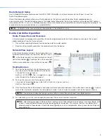
Setting-Up Gain Structure
Setting proper gain structure is necessary to ensure maximum audio clarity and amplifier output performance. To set-up gain
structure, follow the steps outlined below, using a calibrated pink noise source.
1.
Ensure all pre-mix gain, cross-points, and output trim blocks are set to 0 dB
2.
Adjust the Mic/Line Input ANG GAIN blocks so the output meter reads -17dBFS
3.
Adjust the output attenuators, so the output meter reads -17 dBFS
Refer to the
NetPA U 2002 SB User Guide
found on
www.extron.com
for more details on setting-up gain structure.
NOTE:
When setting levels, pay attention to avoid digital clipping.
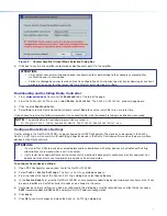
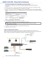
For more information on configuring a NetPA U 2002 SB unit in Dante Controller, see the “Dante Controller” section of the
NetPA U 2002 SB User Guide
found on
www.extron.com
.
10
68-3148-50 Rev. A
11 2020


