background image

MVX VGA A Matrix Switchers • Front Panel Operation

Front Panel Operation

MVX VGA A Matrix Switchers • Front Panel Operation


3-3

3-2

Refer also to the 

MVX VGA A User’s Manual

 at 

www.extron.com

.

Refer also to the 

MVX VGA A User’s Manual

 at 

www.extron.com

.

N

  On some MVX switchers, the video selection button is 

labeled “RGBHV” rather than “Video”.

N

  The front panel controls and indicators have numerous 

functions that are beyond the scope of this setup guide.  
Refer to the 

MVX VGA A Switcher User's Manual

chapter 3, “Operation” for full details.

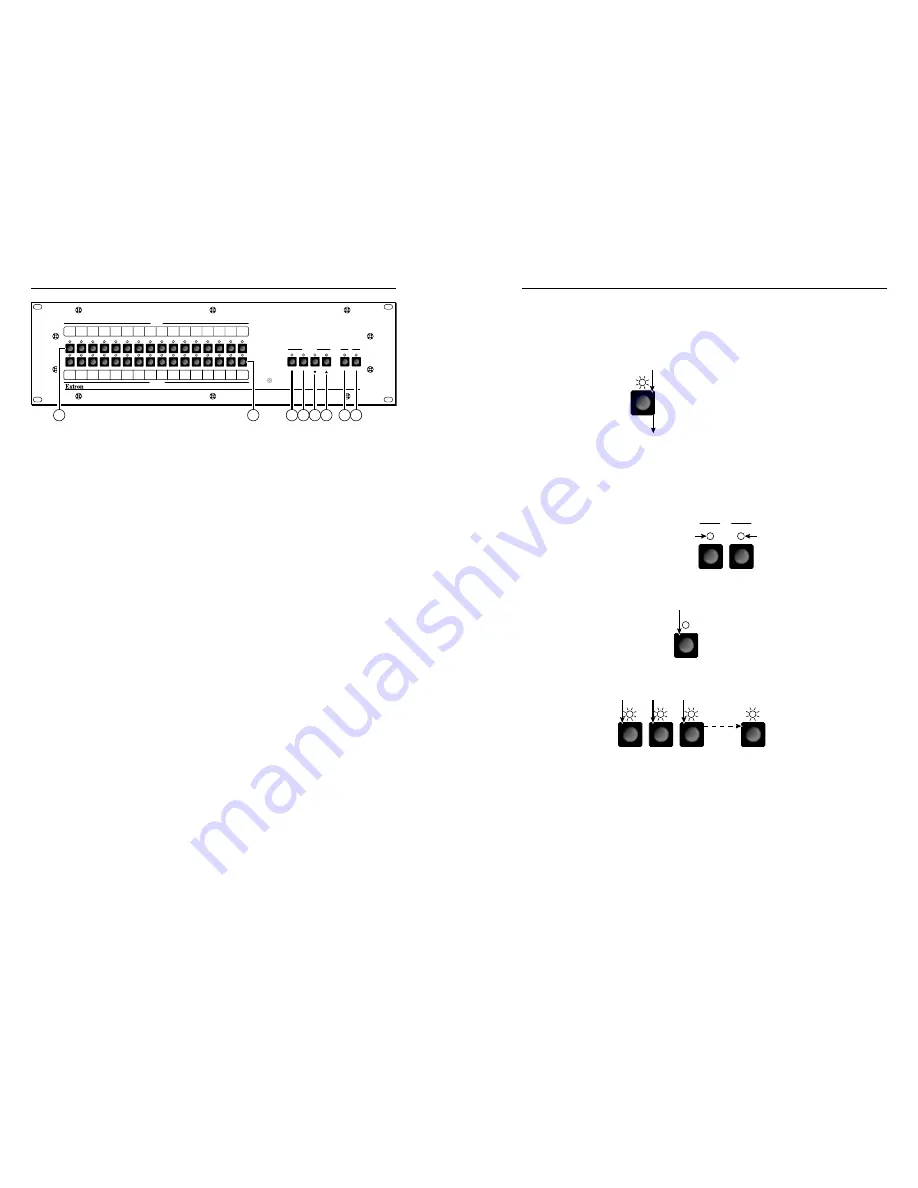
a


Input buttons and LEDs


 Buttons select inputs for front panel 

operations.  LEDs identify selected inputs and indicate other 

miscellaneous displays.

b


Output buttons and LEDs


 Buttons select outputs for front 

panel operations.  LEDs identify selected outputs and indicate 

other miscellaneous displays.

c


Enter button and LED


 Button saves changes that you make 

on the front panel.  LED indicates that a pending change needs 

to be saved.

d


Preset button and LED


 Button selects modes in which you 

can save and recall presets.  LED indicates the preset mode.

e


View (

<

) button and LED


 Button selects a View mode, in 

which you can view the current configuration without making 

inadvertent changes and also mute and unmute outputs.  Button 

also can be used to decrease audio levels.  LED identifies view 

mode.

f


Esc (

>

) button and LED


 Button cancels operations or 

selections in progress and resets the front panel button indicators.  

Button also can be used to increase audio level.  LED flashes 

once to indicate that the escape function has been activated.

g


Video button and LED


 Button selects video for creation of 

ties.  LED indicates that video is selected for tie creation.

h


Audio button and LED


 Button selects audio for creation 

of ties.  Button also selects Audio mode, in which you can 

adjust audio levels.  LED indicates that audio is selected for tie 

creation.  LED also indicates Audio mode is selected.

Creating a Tie

1

Press and release the Esc button to clear any button 

indicators that may be lit.


ESC

Press the Esc button 
to clear all selections.

The LED blinks once.

2

Press and release the Video and/or Audio I/O button(s) to 

select or deselect video and/or audio as desired.

N

  Audio or video can be broken away (tied by itself) by 

selecting 

only

 the Video button or 

only

 the Audio button.


VIDEO

AUDIO

I/O

Lit when selected.

Off when deselected.

Lit when selected.
Off when deselected.

3

Press and release the desired input button.


5

The input LED 

lights to indicate 

the selection.

4

Press and release the desired output button(s).


3

4

8

ENTER

Output LEDs blink to indicate a potential tie. 

Enter LED blinks to indicate the 

need to confirm the change. 

5

Press and release the Enter button.  All button indicators 

turn off.

MVX SERIES

VGA MATRIX SWITCHER 

WITH

 ADPS™

ENTER

PRESET

VIEW

ESC

VIDEO

AUDIO

CONTROL

I/O

OUTPUTS

INPUTS

CONFIG

1

3

4

5

6

7

8

1

3

4

5

6

7

8

9

10

11

12

13

14

15

9

10

11

12

13

14

15

16

16

5 6

7 8

1

2

3 4

Summary of Contents for MVX 1212 VGA A

Page 1: ...n 81 3 3511 7655 81 3 3511 7656 FAX Extron China 400 883 1568 Inside China Only 86 21 3760 1568 86 21 3760 1566 FAX Extron Middle East 971 4 2991800 971 4 2991880 FAX 2009 Extron Electronics All rights reserved Setup Guide 68 521 54 Rev A 11 09 MVX VGA A Computer Video VGA and Audio Matrix Switchers MVX Matrix Switcher Part Numbers These items are included in each order for a MVX A matrix switcher...

Page 2: ... Netz zu trennen sollten Sie alle Netzkabel aus der Rückseite des Gerätes aus der externen Stomversorgung falls dies möglich ist oder aus der Wandsteckdose ziehen Schutz des Netzkabels Netzkabel sollten stets so verlegt werden daß sie nicht im Weg liegen und niemand darauf treten kann oder Objekte darauf oder unmittelbar dagegengestellt werden können Wartung Alle Wartungsmaßnahmen sollten nur von ...

Page 3: ...ns 1 this device may not cause harmful interference and 2 this device must accept any interference received including interference that may cause undesired operation The Class A limits are designed to provide reasonable protection against harmful interference when the equipment is operated in a commercial environment This equipment generates uses and can radiate radio frequency energy and if not i...

Page 4: ...utive Modes 3 5 Selecting Lock mode 2 or toggling between mode 2 and mode 0 3 5 Selecting Lock mode 2 or toggling between mode 2 and mode 1 3 6 Viewing and Adjusting the Input Audio Level and Output Volume 3 6 Viewing Ties and Muting Outputs 3 7 Chapter Four Remote Control 4 1 Selected SIS Commands 4 2 Installing and Starting the Control Program 4 7 Installing the program 4 7 Starting the program ...

Page 5: ...trix Switchers Table of Contents Table of Contents cont d MVX VGA A Matrix Switchers Refer also to the MVX VGA A User s Manual at www extron com 1 Chapter One Introduction About this Manual About the Matrix Switchers ...

Page 6: ...ons simultaneously The switchers are available in four matrix sizes the number of inputs and outputs MVX 128 VGA A 12 inputs by 8 outputs MVX 168 VGA A 16 inputs by 8 outputs MVX 1212 VGA A 12 inputs by 12 outputs MVX 1616 VGA A 16 inputs by 16 outputs INP UT S OU TP UT S RE SE T RS232 RS422 REMOTE LIST ED 1T23 I T E C US 1 2 3 4 5 6 7 8 9 10 11 12 1 2 3 4 5 6 7 8 1 2 3 4 5 6 7 8 9 10 11 12 1 2 3 ...

Page 7: ...laptop s screen shuts off once the external video port is activated See the computer s user s guide for details or contact Extron for a list of common laptop keyboard commands N The MVX VGA 128 A does not have the Sync Impedance switches described below c Sync Impedence switches 168 1212 and 1616 matrix sizes The Sync Impedance switches compensate the output 1 through 8 impendance for different ca...

Page 8: ... MATRIX SWITCHER WITH ADSP TM CONFIG 8 h Configuration port If desired connect a control or computer to the front panel Configuration RS 232 port Use an optional 9 pin D to 2 5 mm mini jack TRS RS 232 cable part 70 335 01 3 Chapter Three Front Panel Operation Creating a Tie Saving or Recalling a Preset Setting the Front Panel Locks Executive Modes Viewing and Adjusting the Input Audio Level and Ou...

Page 9: ...tions or selections in progress and resets the front panel button indicators Button also can be used to increase audio level LED flashes once to indicate that the escape function has been activated g Video button and LED Button selects video for creation of ties LED indicates that video is selected for tie creation h Audio button and LED Button selects audio for creation of ties Button also select...

Page 10: ...ode 0 The front panel is completely unlocked Lock mode 1 All changes are locked from the front panel except for setting Lock mode 2 Some functions can be viewed Lock mode 2 Basic functions are unlocked Advanced features are locked and can be viewed only Basic features consist of m Making ties m Saving and recalling presets m Setting input audio gain and attenuation m Changing Lock modes Advanced f...

Page 11: ...ld the Audio button until it flashes AUDIO AUDIO Audio LED blinks Hold 2 seconds 2 Press an input button for input level or output button for volume Refer to the MVX VGA A Switcher User s Manual chapter 3 Operation to read the displayed value OUTPUTS 5 1 2 3 4 Press an input button to adjust gain attenuation or Press an output button to adjust the output volume Output LEDs display gain attenuation...

Page 12: ...n Front Panel Operation cont d 3 8 MVX VGA A Matrix Switchers Refer also to the MVX VGA A User s Manual at www extron com 4 Chapter Four Remote Control Selected SIS Commands Installing and Starting the Control Program Button Label Generator Program ...

Page 13: ... Manual at www extron com Selected SIS Commands The switchers have Simple Instruction Set SIS commands that you can use for operation and configuration You can run these commands from a PC connected to either of the switcher s serial ports See f page 2 3 and h page 2 4 for connection information ...

Page 14: ...nd audio X X OutX InX All Tie input X s video and audio to output X Example 1 3 Out03 In01 All Tie input 1 video and audio to output 3 Tie input X to output X RGBHV X X OutX InX RGB Tie RGB only video breakaway Example see 3rd Note above 10 4 Out04 In10 RGB Tie input 10 RGB to output 4 Tie input X to output X video X X OutX InX Vid Tie video only video breakaway Example see 3rd Note above 7 5 Out0...

Page 15: ... All other outputs are unmuted N The Mut portion of the response appears only when the switcher is in Verbose mode 3 See the Verbose mode command on page 4 6 N X Output number 01 maximum number of outputs for your model X Mute 0 off unmuted 1 on muted X Video audio mute 0 no mutes 2 audio mute 1 video mute 3 video and audio mute Command ASCII command host to switcher Response switcher to host Addi...

Page 16: ...X Information requests Information request I VX XX AX XX VX XX video size AX XX audio size Request part number N X1 Query controller firmware version Q X1 Example Q 1 23 The factory installed controller firmware version is 1 23 sample value only Verbose mode Set verbose mode EX1 CV VrbX1 Read verbose mode ECV X1 N X Lock mode 0 1 or 2 X Inputs Total number of inputs for this switcher X Outputs Tot...

Page 17: ...cted to either of the switcher s serial ports See f page 2 3 and h page 2 4 for connection information The program must be installed on a Windows based computer and cannot be run from the DVD N For details on operating the program refer to the MVX VGA A Switcher User s Manual chapter 5 Matrix Software Installing the program 1 Insert the disk into the drive The Extron software DVD window should app...

Page 18: ...heck the baud rate displayed in the comm port selection window If you need to change the baud rate click the Baud button and double click the desired baud rate Click OK The Matrix Switchers Control Program is ready for operation Button Label Generator Program The Button Label Generator software creates labels that you can place in the translucent covers above and below the front panel input and ou...

Page 19: ...MVX VGA A Matrix Switchers Remote Control Remote Control cont d 4 10 Refer also to the MVX VGA A User s Manual at www extron com ...

Reviews: