background image

4

IPCP Pro PCS1 • Setup Guide (Continued)

Panels and Locations of Features

Front Panel Features

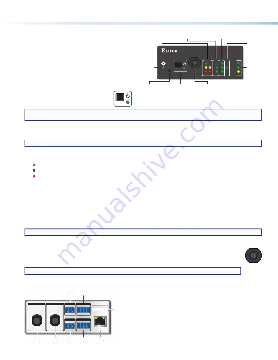
See figure 2 at right for the front panel features and their  
locations. 
The LED indications are described and shown in 

Cabling 

and Features

 starting on page 5 paired with descriptions 

of the corresponding ports. For reset button and reset 
mode information, see the 

IPCP Pro Series User Guide

.

Power button (switch) and LED

The front panel power button (switch) provides  
a convenient way to manually turn switched 
AC power output on or off for the rear panel 
AC power output cable. 

NOTE:

  The button is not a safety disconnect device. In case of an emergency, disconnect AC power from the power input 

(appliance inlet) of the connected equipment. 

The IPCP Pro PCS1 can be configured (using Global Configurator or Global Scripter) to monitor the power output condition and 
to alert users in the event of a power fault interruption. The IPCP Pro PCS1 can be set up to monitor the circuit breaker and also 
the current load at the switched AC power output port.

NOTE:

  The power output state setting persists after and is retained during a power cycle.

LED indications

The LED lights to indicate the power output state as follows:

• 

  Lit green: power output is enabled.

• 

  Off (dark): power output is disabled.

• 

  Lit red: a fault condition is detected, and power output is disabled.

Front panel lockout (executive mode)

To prevent unauthorized use, this button can be locked (disabled) via a front panel lockout mode (executive mode) that can be 
enabled or disabled by one of two methods:

• 

Using software, as part of the configuration or when programming actions, monitors or schedules 

• 

Holding down the power button switch for 3 seconds

The power LED blinks three times to indicate the lockout mode has been enabled or disabled.
When the front panel is locked, if the 

Power

 button is pressed, the power LED blinks three times to indicate that the button is 

locked, and the unit does not change power states as a result of the button press.

NOTE:

  The executive mode state (on or off) persists after and is retained during a power cycle.

Circuit breaker

The front panel features a 10 A rated circuit breaker. When a fault condition occurs, the breaker is triggered, which  
stops power output. This condition can be monitored and the system can be configured (using available commands) 
to send an alert e-mail or perform some other action. After you correct the cause of the overcurrent condition, press 
the 

Breaker

 button to manually reset the circuit breaker.

NOTE:

  The circuit breaker and the 

Reset

 button are not affected by front panel lockout (executive mode) settings.

Rear Panel Features

LAN

IPCP PRO PCS1

IR/S

S G

eBUS

PWR OUT = 6W

DIGITAL I/O

1   2   3   G

G

Tx Rx

COM

50-60Hz

50-60Hz

100-240V ~ 10A MAX

100-240V ~ 10A MAX

INPUT

OUTPUT

-S

+V +S

G

MAC: 00-05-A6-

XX-XX-XX

S/N:  #######    E######

C

C

C

C

IPCP Pro PCS1

A

A

A

A

B

B

B

B

D

D

D

D

F

F

F

F

E

E

E

E

G

G

G

G

H

H

H

H

A


Power input

 (attached cable) — Powers the IPCP Pro PCS1.

B


AC power output

 (attached cable) — Provides switched 

(controlled) AC power output to another device.

c


3-pole COM port

 (RS-232-only), page 6

D


Digital I/O ports

 (digital input/output), page 7

E


IR/serial output port

, page 6

F


eBUS port

, page 7

G


LAN connector and LEDs

 (Ethernet), page 6

H


MAC address

, page 6

Figure 3. 

IPCP Pro PCS1 Rear Panel

10

PR

E

S

S


  T

O       R

E

S

E

T

BREAKER

Tx

Rx

COM

1

2

3

I/O IR/S

R

1000

LINK

ACT

IPCP PRO PCS1

LIMIT

eBUS

POWER

OVER

E

L

B

COM (Serial) LEDs

Digital I/O LEDs

Reset Button


(recessed)

AC Power Button


and LED

Circuit 

Breaker

eBUS 

LEDs

LAN/ 

Network

LEDs

IR/Serial 

LED

Power 

LED

Figure 2. 

IPCP Pro PCS1 Front Panel

POWER

10

BREAKER

10

PR

E

S

S


  T

O       R

E

S

E

T

When an overcurrent condition 
occurs, such as a short circuit 
or circuit overload

Summary of Contents for IPCP Pro PCS1

Page 1: ... applications These control processors support multiple TouchLink Pro touchpanel interfaces over a standard Ethernet network The software applications are available at www extron com This guide provides instructions for an experienced installer to install an IPCP Pro PCS1 control processor and to create a basic configuration CAUTION This product is intended for indoor use only ATTENTION Ce produit...

Page 2: ... project and configuration If TouchLink Pro or third party touchpanels are part of the system start and use GUI Designer to design save and build the graphical user interface GUI layout for the touchpanels NOTE To redeem activate a LinkLicense go to www extron com llredeem and follow the online instructions Using GC create a new GC Professional or GC Plus project and configure the control processo...

Page 3: ...red control processor in the list and select it Network Communication Setup Connect the PC and the LAN port of the control processor to the same network Apply power to all devices Use the Set IP feature in Toolbelt or use the Toolbelt Manage Network Settings tab feature to enter the IP address and subnet address then configure other network settings as needed Figure 1 Network Setup Mounting Secure...

Page 4: ...nks three times to indicate the lockout mode has been enabled or disabled When the front panel is locked if the Power button is pressed the power LED blinks three times to indicate that the button is locked and the unit does not change power states as a result of the button press NOTE The executive mode state on or off persists after and is retained during a power cycle Circuit breaker The front p...

Page 5: ...0V 10A MAX INPUT OUTPUT Rear Panel Switched 100 240 VAC 10 A Max Power Output Front panel Power LED appears Lit green when power output is enabled unit outputs power Off when power output is disabled power output is off Lit red when a power output overcurrent condition is detected the circuit breaker has been tripped and power output is disabled Front panel Power button controls power output avail...

Page 6: ...ports Default login credentials Username admin Password extron IPCP IP address 192 168 254 250 Gateway IP address 0 0 0 0 Subnet mask 255 255 255 0 DNS address 127 0 0 1 DHCP client off Link speed and duplex level autodetected Data rates 10 100 1000Base T PC The control processor is assigned a unique user hardware ID number MAC address for example 00 05 A6 05 1C A0 You may need this address during...

Page 7: ...daisy chain star or combination Wire the connectors the same at both ends for every eBUS device See the eBUS Technology Reference Guide for the recommended distance from the control processor to the last eBUS device and maximum quantity of devices per control processor The IPCP Pro can provide power to the button panel devices Front Panel eBUS Limit LED amber Lights steadily and remains lit while ...

Page 8: ...n for about 3 seconds until the Power LED blinks once Release and press the Reset button momentarily for 1 second within 1 second Nothing happens if the momentary press does not occur within 1 second The LED blinks 2 times if the program is starting The LED blinks 3 times if the program is stopping This mode allows you to restart any programs stopped by an IP settings reset Toggle DHCP Client Pres...

Page 9: ...or the Extron S3 Control Systems Support Hotline 1 800 633 9877 Locating Software Firmware and Driver Files on the Extron Website There are three main ways to find software firmware and device drivers within www extron com Via links from the web page for the specific product Via the Download Center page Click on the Download tab at the top of any page within www extron com Via links from search re...

Page 10: ...chedules timers macros and local variables Add touchpanels or other interfaces if used to the project Configure ports on the control processor Import GUI layouts and configure the touchpanels or other interfaces Test the system make adjustments finalize configuration Save the project Build and upload the configuration to the control processor If desired or required install a new security certifica...

Reviews: