


5
IN1808 Series Configuration
To configure IN1808 Series, use the front panel controls, the
on-screen display (OSD) menu, internal web pages, PCS, or SIS
commands.
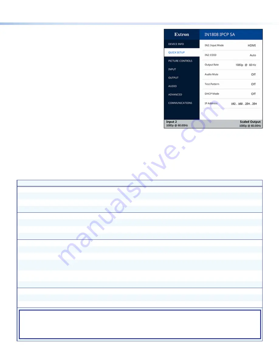
On-screen Display (OSD) Menu System
To configure IN1808 Series using the OSD menu, connect a display
to either HDMI output 1A or to a DTP/XTP matrix switcher/HDBaseT
compatible device. The OSD menu consists of eight submenus accessed
using the front panel
Menu
or
Enter
button (see the example at right).
Extron Product Configuration Software
To configure IN1808 scalers using PCS, install the software (available on
the Extron website,
www.extron.com
) to a PC connected to the scaler
via Ethernet or front panel USB Config port. After the installation, start the
program. For full instructions, press <
F1
> on the keyboard or click the
?
button in the software and select
Help
File
.
Internal Web Pages
To configure the IN1808 Series using the factory-installed web pages in a web browser (see the example at right), connect the
AV LAN connector (IPCP models) or LAN connector (base model) on the IN1808 to a LAN or WAN. The default IP address is
192.168.254.254.
Basic SIS Command Table
To configure IN1808 Series with specific SIS commands via an RS-232, USB, or Ethernet connection, use the Extron DataViewer
utility or a control system to send and receive SIS commands. The table below lists a selection of SIS commands. For a full list of
SIS commands and variables, see the
IN1806 and IN1808 Series User Guide
at
www.extron.com
.
Command
ASCII Command
Response
Additional Description
Input Selection
Select audio and video input
X!
*1!
In
X!
*1
•
All
]
Select audio and video from input
X!
to the output.
Select video input only
X!
*1%
In
X!•
1Vid
]
Select the video only from input
X!
to the output.
Select audio input only
X!
*1$
In
X!•
1Aud
]
Select the audio only from input
X!
to the output.
Auto-Image
Execute Auto-Image
™
1*0A
Img*0
]
Execute an Auto-Image (follows aspect setting).
Execute Auto-Image and fill
1*1A
Img*1
]
Execute an Auto-Image and fill the output raster.
Execute Auto-Image and follow
1*2A
Img*2
]
Execute an Auto-Image and follow the input aspect ratio.
Auto-Switch Mode
Set Auto-Switch mode
EX3)
AUSW
}
Ausw
X3)]
Select Auto-Switch mode
X3)
.
View Auto-Switch mode
E
AUSW
}
X3)]
View the current Auto-Switch mode.
Set Auto-Switch priority
E
P
X3!
1
...
X3!
8
AUSW
}
Ausw
P
X3!
1
...
X3!
8
]
Set priority
X3!
for input selection. Lists inputs in order of
priority, from highest to lowest.
View Auto-Switch priority
E
P
AUSW
}
X3!
1
...
X3!
8
]
View Auto-Switch priority. Lists inputs in order of priority,
from highest to lowest.
View memory priority
E
O
AUSW
}
X3!
1
...
X3!
8
]
View Auto-Switch memory priority, from highest to lowest
Output Scaler Rate
Set output rate
E
1*
X2!
RATE
}
Rate1*
X2!]
Select output resolution and refresh rate
X2!
.
View output rate
E
1RATE
}
X2!]
View the output rate.
KEY:
X!
= Input selection
1
through
8
X2!
= Output resolution and rate
See the EDID Emulation and Output Rate table in the
IN1806 and IN1808 Series User Guide
.
X3)
= Auto-Switch mode
0
= disabled (default),
1
= user defined priority,
2
= input memory priority (most recently
detected
input)
X3!
= Input numbers for Auto-Switch priority
1
through
8


