background image


DVC RGB-HD A • Installation

6

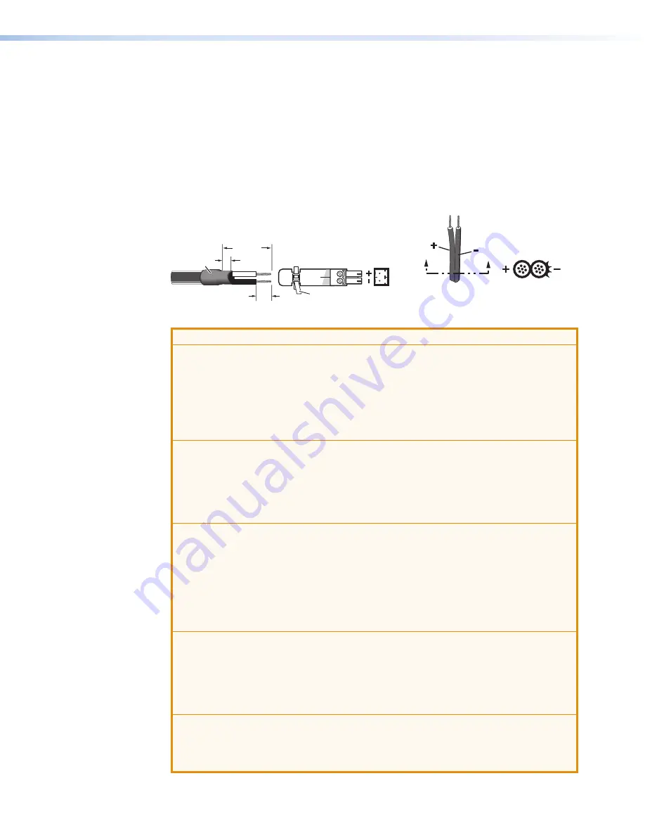
Follow these instructions to wire the provided 2-pole captive screw connector to your power 
supply:

1. 

Cut the DC output cord to the length needed.

2. 

Strip the jacket to expose 3/16” (5 mm) of the conductors. 

3. 

Slide the leads into the supplied 2-pole captive screw plug and secure them, using a 
small screwdriver.

4. 

To verify the power cord polarity before applying power to the unit, connect the power 
supply to AC power with no load and check the output with a voltmeter.

5. 

Use the supplied tie wrap to strap the power cord to the extended tail of the connector.

Captive Screw Connector

Tie Wrap

Heat
Shrink

1/8"

(3 mm)

7/8"

(22 mm)

3/16"

(5 mm) Max.

A

A

Power Supply

Output Cord

Ridges

Smooth

SECTION  A–A


Figure 4. 

Wiring the Power Connector

ATTENTION:

• 

Always use a power supply supplied and or specified by Extron. Use of an 
unauthorized power supply voids all regulatory compliance certification and may 
cause damage to the supply and the end product.

• 

Utilisez toujours une source d’alimentation fournie ou recommandée par Extron. 
L’utilisation d’une source d’alimentation non autorisée annule toute conformité 
réglementaire et peut endommager la source d’alimentation ainsi que le produit 
final.

• 

If not provided with a power supply, this product is intended to be supplied by a 
UL Listed power source marked “Class 2” or “LPS” and rated output 12 VDC, 
minimum 0.2 A.

• 

Si le produit n’est pas fourni avec une source d’alimentation, il doit être alimenté 
par une source d’alimentation certifiée UL de classe 2 ou LPS, avec une tension 
nominale 12 Vcc, 0.2 A minimum.

• 

The installation must always be in accordance with the applicable provisions of 
National Electrical Code ANSI/NFPA 70, article 725 and the Canadian Electrical 
Code part 1, section 16. The power supply shall not be permanently fixed to 
building structure or similar structure.

• 

Cette installation doit toujours être en accord avec les mesures qui s’applique 
au National Electrical Code ANSI/NFPA 70, article 725, et au Canadian Electrical 
Code, partie 1, section 16. La source d’alimentation ne devra pas être fixée de 
façon permanente à une structure de bâtiment ou à une structure similaire.

• 

Power supply voltage polarity is critical. Incorrect voltage polarity can damage 
the power supply and the unit. The ridges on the side of the cord (see figure 4) 
identify the power cord negative lead.

• 

La polarité de la source d’alimentation est primordiale. Une polarité incorrecte 
pourrait endommager la source d’alimentation et l’unité. Les stries sur le côté du 
cordon permettent de repérer le pôle négatif du cordon d’alimentation.

• 

To verify the polarity before connection, plug in the power supply with no load 
and check the output with a voltmeter.

• 

Pour vérifier la polarité avant la connexion, brancher l’alimentation hors charge et 
mesurer sa sortie avec un voltmètre.

Summary of Contents for DVC RGB-HD A

Page 1: ...User Guide DVC RGB HD A Video Converters RGB HDMI Converter 68 2898 01 Rev D 04 21...

Page 2: ......

Page 3: ...lt PowerCage PURE3 Quantum ShareLink Show Me SoundField SpeedMount SpeedSwitch StudioStation System INTEGRATOR TeamWork TouchLink V Lock VideoLounge VN Matrix VoiceLift WallVault WindoWall XPA XTP XTP...

Page 4: ...Afin de s assurer de la compatibilit entre FCC Classe A et CE les c bles STP et les connecteurs STP sont n cessaires NOTES This 1st paragraph is for TP ONLY delete for all others products This unit wa...

Page 5: ...guide the character 0 is the number zero and O is the capital letter o Computer responses and directory paths that do not have variables are written in the font shown here Reply from 208 132 180 48 by...

Page 6: ...ion and Control 11 Communication Port 11 Using SIS Commands 11 DVC initiated Message 11 Error Responses 12 Using the Command and Response Table 12 Symbol Definitions 13 Command and Response Table for...

Page 7: ...DVC RGB HD A Contents vii...

Page 8: ...s the adaptation or integration of legacy VGA products into an all digital audio video system Features The DVC RGB HD A provides the following features Conversion of analog RGBHV to HDMI Adapts analog...

Page 9: ...le of a DVC RGB HD A application HDMI with Audio DVC RGB HD A INPUT CONFIG DTP CROSSPOINT 4K SERIES DIGITAL PRESENTATION SWITCHER Extron CONTROL I O AUDIO VIDEO LOGO SELECT ENTER PRESET VIEW ESC 1 2 3...

Page 10: ...Mount the unit in a rack or to furniture see Mounting beginning on page 32 3 Connect the input Connect an RGBHV source to the front panel VGA input connector see figure 2 B on the next page 4 Optional...

Page 11: ...es d charges lectrostatiques ESD peuvent endommager l quipement m me si vous ne pouvez pas le sentir le voir ou l entendre Front Panel DVC RGB HD A A A A C C C INPUT B B B Figure 2 DVC RGB HD A Front...

Page 12: ...V output is active only when a source is connected to the input If no source is connected the 5 V output is disabled This may be necessary for some sinks to enter power save mode Secure the HDMI outpu...

Page 13: ...er source marked Class 2 or LPS and rated output 12 VDC minimum 0 2 A Si le produit n est pas fourni avec une source d alimentation il doit tre aliment par une source d alimentation certifi e UL de cl...

Page 14: ...mention contraire les adaptateurs AC DC ne sont pas appropri s pour une utilisation dans les espaces d a ration ou dans les cavit s murales Securing the HDMI Connector Using the LockIt Cable Lacing B...

Page 15: ...Figure 5 Connecting to the Config Port 2 When the DVC is first connected to a particular USB port on the computer one of the following windows may open NOTE If you have uploaded the PCS software to yo...

Page 16: ...e DVC is connected to each USB port It does not reopen until you connect the DVC to a different USB port Windows 7 and later A pop up notification appears on the Windows taskbar informing you that Win...

Page 17: ...characteristics The DVC has nine slots to which EDIDs can be assigned VGA EDIDs slots 1 through 7 These factory provided EDID files can be assigned to slots 1 through 7 via SIS commands Each EDID file...

Page 18: ...e See Connecting for USB Control on page 8 to connect to the USB port Using SIS Commands SIS commands consist of one or more characters per command field They do not require any special characters to...

Page 19: ...E17 Invalid command for signal type Using the Command and Response Table The Command and Response Table for SIS Commands beginning on page 15 lists the commands that the DVC RGB HD A converter recogni...

Page 20: ...from a signal change or a setting adjustment made via another interface For example the DVC can send out a notice of a change in some setting without receiving a query via your PC That change could h...

Page 21: ...0 Hz X X Pixel phase 0 to 63 Default is 32 X X Total pixels Default is 255 depends on the input rate X Horizontal or vertical start 0 to 255 Default is 128 X1 Output format 0 HDMI RGB full 4 4 4 defau...

Page 22: ...odes 2 and 3 Sig X X Show signal presence on input and output For X 0 No signal detected 1 Signal detected EDID Minder Assign EDID slot to input E A X EDID Edid A X Assign EDID resolution and refresh...

Page 23: ...ay Increment pixel phase value E 1 PHAS Phas 1 X Increase the pixel phase value by 1 Decrement pixel phase value E 1 PHAS Phas 1 X Decrease the pixel phase value by 1 View pixel phase value E 1 PHAS X...

Page 24: ...cal start value by 1 Decrement vertical start value E 1 VSRT Vsrt 1 X Decrease the vertical start value by 1 View vertical start value E 1 VSRT X In verbose modes 2 and 3 Vsrt 1 X View the vertical st...

Page 25: ...DVC RGB HD A In verbose modes 2 and 3 Inf01 60 1614 01 View the unit model name Query model description 2I VGA TO HDMI CONVERTER In verbose modes 2 and 3 Inf02 VGA TO HDMI CONVERTER View the unit mode...

Page 26: ...ands Downloading the PCS Software from the Website To use PCS download the latest version of the program from the Extron Web page and install it on the PC that will be connected to the DVC as describe...

Page 27: ...fill in the required information then click the Download pcss_vnxn exe button 7 If the File Download Security Warning window appears click Run to begin downloading the installer file NOTE If you want...

Page 28: ...llowing Access the program from the Start menu on your computer as follows a Click Start on your computer screen b Select All Programs from the Start menu c From the All Programs menu select Extron El...

Page 29: ...e release of new software revisions Before updating any Extron product to the latest revision level be sure to read the supplied release notes or contact Extron Technical Support to determine if your...

Page 30: ...dy have Firmware Loader installed on your computer download it as follows 1 Go to www extron com and click the Download tab 2 On the Download screen click the Software link see figure 14 1 in the left...

Page 31: ...te Configuration and Control 24 3 On the Download Center screen click the F link see figure 15 1 then locate Firmware Loader and click its Download link 2 Figure 15 Firmware Loader Links on the Downlo...

Page 32: ...nload Center page that appears next fill in the required information then click the Download fw_loader_vnxn exe button where nxn is the Firmware Loader version number 6 Follow the instructions on the...

Page 33: ...h your e mail address and password If you do not have an Extron account with a password follow the instructions on the screen to obtain one then proceed to step 6 6 On the Download Center page that ap...

Page 34: ...re and install it on your computer see Downloading and Installing the DVC RGB HD A Firmware on the previous page 4 Open the Firmware Loader on your computer The Firmware Loader window opens with the A...

Page 35: ...e file which has an S19 extension and double click it ATTENTION Valid firmware files must have the file extension S19 A file with any other extension is not a firmware upgrade for this product and cou...

Page 36: ...added to the Device panel see figure 20 2 of the Firmware Loader window and the Add Device window remains open b For each additional device that you want to add to the Firmware Loader window repeat s...

Page 37: ...gure 21 1 shows the remaining and elapsed time for the update The Total Progress panel 2 displays the percentage of upload time that has elapsed a progress bar with Uploading above it and the rate of...

Page 38: ...Time field see figure 22 1 of the Transfer Time panel shows 00 00 00 the Progress column 2 shows 100 Completed is displayed above the progress bar 3 and in the Status column 4 and the new firmware ver...

Page 39: ...delines pertain to the installation of the DVC RGB HD A in a rack Elevated operating ambient temperature If the equipment is installed in a closed or multi unit rack assembly the operating ambient tem...

Page 40: ...other furniture 3 Mark the location of the screw holes in the brackets on the mounting surface 4 Drill pilot holes 3 32 inches 2 5 mm in diameter and 1 4 inch 6 3 mm deep in the mounting surface at th...

Page 41: ...ica 3rd Floor South Tower 160 Jan Smuts Avenue Rosebank 2196 South Africa This Limited Warranty does not apply if the fault has been caused by misuse improper handling care electrical or mechanical ab...

Reviews: