8.
Connect control devices.
Connect your computer to one of the following communication ports to configure and control the
switcher via SIS commands or Product Configuration Software (PCS):
•
RS‑232 port
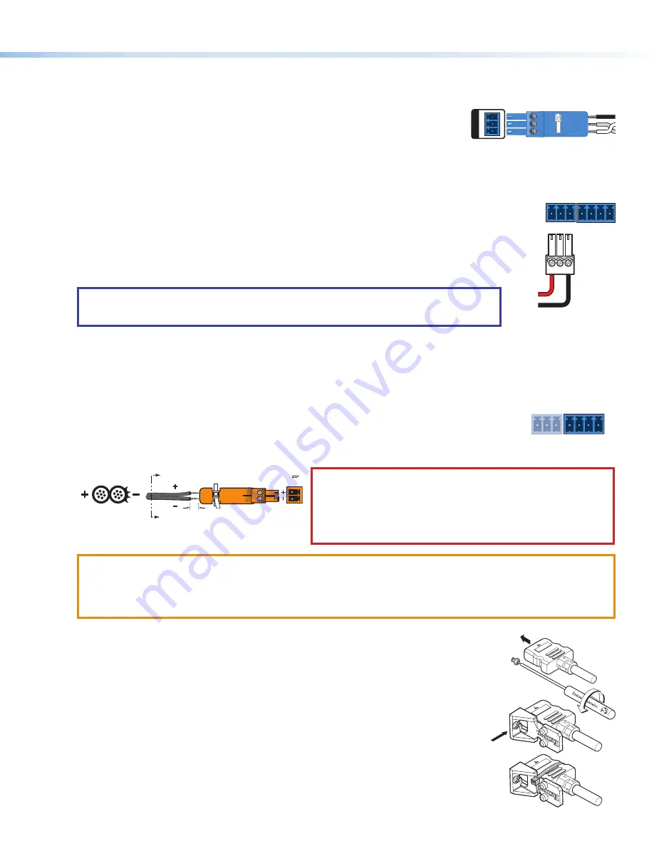
— Connect the unterminated transmit, receive, and ground wires of the
RS-232 cable to the three pins on the provided 3-pole captive screw connector, as shown
in the diagram on the right. Insert the connector into the rear panel Remote port (
the other end of the cable into your computer serial port. Protocol for the RS-232 port:
•
9600 baud
•
8 data bits
•
no parity
•
Config port
— Connect a USB mini-B cable to the front panel USB port (see
, on the next page) for USB control.
9.
Connect a contact closure device
(optional). Connect a push-button contact closure device to a
, on page 1) to enable input switching via contact closure.
a.
Wire and plug one of the provided blue, 3.5 mm, 3-pole connectors into a Contact/Tally port
representing input 1 or input 2 on the DTP2 T 212.
•
C
= Contact closure input
•
G
= Contact and Tally Ground
•
T
= Tally output
b.
Press the button on the contact closure device to switch the connected input to the output.
TIP:
The Contact and Tally ports can be used with Extron Show Me cables. For each cable, connect
the red wire to the Contact Closure pin and the black wire to the Tally Out pin (see diagram on the
right).
10.
Connect an indicator device to the Tally Out port
(optional). To identify the currently selected input when the front panel
buttons are not visible, connect a device such as an LED to the Contact/Tally port (
). When the input you are using is
selected, the corresponding tally out pin shorts to ground, which activates the connected indicator.
Wire and connect one of the provided blue, 3.5
mm, 4-pole connectors into a Contact In/Tally Out port.
•
C
= Contact closure input
•
G
= Contact and Tally Ground
•
T
= Tally output
•
+V
= +5 VDC (Insert the power wire for the contact indicator device into the +V port.)
CONTACT /
TALLY
1
C G T
C G
+V
T
2
11.
If necessary, wire a 2-pole captive screw connector to your power supply as shown in figure 4 (see
on page 1).
SECTION A–A
Ridges
Smooth
A
A
3/16"
(5 mm) Max.
POWER
12V
--A MAX
Figure 4.
Wiring the Power Connector
CAUTION:
The DC output cables must be kept separate from each
other while the power supply is plugged in. Remove power before
wiring.
ATTENTION :
Les câbles de sortie CC doivent être séparés les uns
des autres tant que la source d’alimentation est branchée. Coupez
l’alimentation avant d’effectuer un raccordement.
ATTENTION:
•
Do not connect any external power supplies until you have read the Attention notifications in the Power Supply section of
the DTP2 T/R 211 User Guide.
•
Ne branchez pas de sources d’alimentation externes avant d’avoir lu les mises en garde dans la section « Power Supply »
du DTP2 T/R 211 User Guide.
12.
Power on the output display.
13.
Connect power to the switcher.
14.
Power on the source devices.
LockIt Lacing Brackets
Use the included LockIt Lacing Brackets to securely fasten the HDMI cables to each device as follows
.
1
Plug the HDMI cable into the rear panel connection.
2
Loosen the HDMI connection mounting screw from the panel enough to allow the LockIt lacing
bracket to be placed over it. The screw does not have to be removed.
3
Place the LockIt lacing bracket on the screw and against the HDMI connector, then tighten the screw
to secure the bracket.
4
CONTACT /
TALLY
1
C G T
Red
Black
Show Me Cable
C G
+V
T
2
1
3
4
2
5
REMOTE RS-232
Tx
Rx
RS-232
G
REMOTE
3


