


2. Align the circular holes on one end of the KT-150173-01 extension arm against the large holes on the
1-axis tilt part.
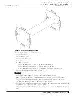
Figure 16: Circular holes on the KT-150173-01 extension arm
Callout
Description
1
Circular holes on the KT-150173-01 extension arm that is used to attach to the
KT-147407-02 1-axis tilt part, to attach to the wall, and to KT-147407-02 pole
part.
3. Attach the KT-150173-01 extension arm to the 1-axis tilt part by using two hex-head M12 stainless-
steel screws and two hex-head M12 stainless-steel nuts.
4. Attach the KT-147407-02 pole part to the other end of the KT-150173-01 extension arm using two
M12 screws and M12 hex-nuts.
5. Insert the 0.5 in. (12.7 mm) wide stainless-steel cable clamps through the long slots on the sides of
the KT-147407-02 pole part.
6. Position and insert the ends of the cable clamps around the pole.
7. Tighten the clamp screws to a torque of 11 in-lbs.
Attach the Access Point to a Pole Using the
KT-147407-02 Bracket Parts and the KT-150173-01
Extension Arm
Install the Access Point
34
ExtremeWireless™ AP460i/e Access Points