


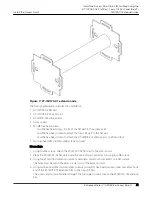


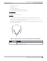


Figure 7: KT-150173-01 extension arm
The following hardware is required for installation:
•
KT-147407-02 flat part
•
KT-147407-02 1-axis tilt part
•
KT-150173-01 extension arm
•
Access point
•
Ten M6 hex-head screws
◦
Two M6 hex-head screws to attach the flat part to the access point
◦
Four M6 hex-head screws to attach the 1-axis tilt part to the flat part
◦
Four M6 hex-head screws to attach the KT-150173-01 extension arm to a flat surface
•
Two hex-head M12 stainless-steel screws and nuts
Procedure
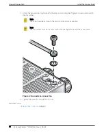
1. Using two M6 screws, attach the KT-147407-02 flat part to the access point.
2. Place the KT-147407-02 flat part inside the 1-axis tilt part, and attach it using four M6 screws.
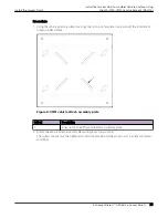
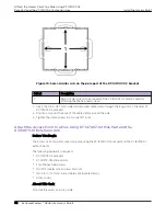
3. Using the KT-150173-01 extension arm as a template, mark four hole centers on a flat surface.
The holes must be within the semi-circular cuts of the extension arm.
4. Using two hex-head M12 stainless-steel screws and two M12 hex-head stainless-steel nuts, attach one
end of the KT-150173-01 extension arm to the 1-axis tilt part.
The screws and nuts are fastened through the two large circular holes on the KT-150173- 01 extension
arm.
Install the Access Point
Install the Access Point to a Flat Surface Using the
KT-147407-02 Flat Part, 1-axis Tilt Part, and the KT-
150173-01 Extension Arm
ExtremeWireless™ AP460i/e Access Points
21