background image

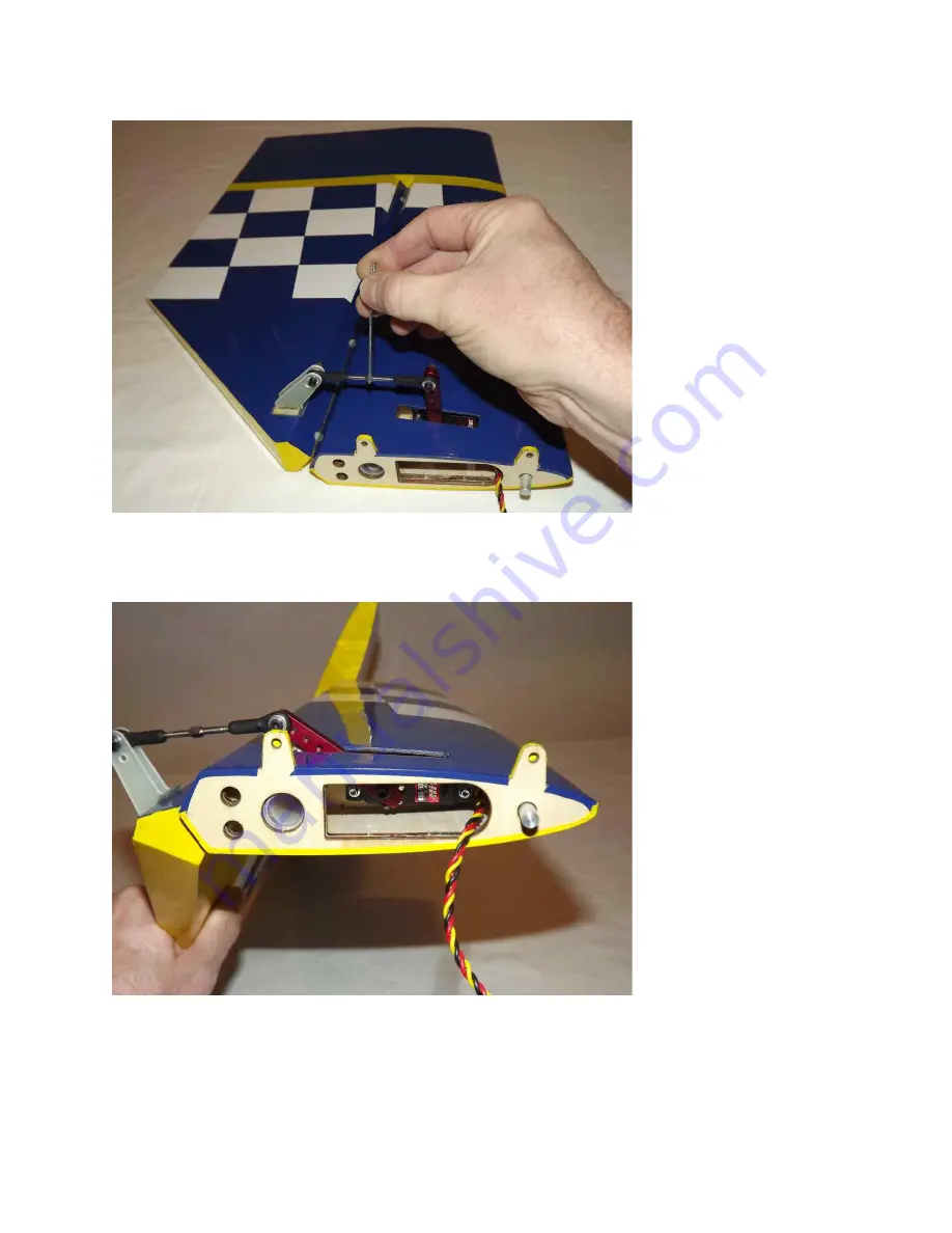
21. With the servo arm centered (as described in Step 17), adjust the turnbuckle on

the control rod until the elevator is in the neutral position. 

22. Set the servo endpoints to achieve maximum travel. You may need to enlarge the

size of the servo arm exit slot.  Repeat these steps for the other stab assembly. 

Note:  Now is a  good time  to take a  covering  iron  and go  over  all  of the seams with  a
medium  heat  setting,  paying  special  attention  to  the  ends  of  thin  trim  stripes.  At  this
point, clean the 2 elevator/stab assemblies with Windex and a soft cloth and put them
away in their protective bag.

17

Summary of Contents for MXS-EXP

Page 1: ...94 MXS EXP ARF Assembly Manual Copyright 2015 Extreme Flight 1 ...

Page 2: ...tics in order to be properly insured and operate your model at AMA sanctioned flying fields only If you are not willing to accept ALL liability for the use of this product please return it to the place of purchase immediately Extreme Flight RC Ltd guarantees this kit to be free of defects in materials and workmanship for a period of 30 DAYS from the date of purchase All warranty claims must be acc...

Page 3: ...s ability to perform the full range of full stall high alpha maneuvers and aggressive gyroscopic tumbling maneuvers The MXS is rewriting the rule book on ultra aggressive 3D maneuvers Unrivaled in pitch and yaw authority the MXS will be the machine that introduces a whole new level of gyroscopic gyrations and insane tumbles to the hardcore 3D masses Rock solid in all aspects of current 3D maneuver...

Page 4: ...block and sandpaper 5 x Hitec HS 9380TH MKS HV 777 HBL 380 X8 or comparable servos 1 x standard size servo for the throttle 2 x 1 5 single aluminum Servo Arms for the ailerons 2 x 2 single aluminum arms for the elevators 1 x 4 double offset aluminum arm for the rudder 2 x 6 Servos Extensions 2 x 12 Servo Extensions 1 24 Servo Extension 2 x 36 Servo Extensions If you need to remove the stabs for tr...

Page 5: ...rives at your door step it will have been handled by a lot of people Occasionally there are small dings or imperfections on some of the surfaces An effective method to restore these imperfections to original condition is to use a very fine tipped hypodermic needle and inject a drop of water under the covering material and into the ding in the wood Apply heat to the area with a sealing iron and the...

Page 6: ... from the elevator hardware package Use a sharp 11 blade or soldering iron to remove the covering over the 2 slots for the elevator control horns on the bottom of the elevator surface 2 Insert the 2 control horns into the base plate and trial fit the horns into the slot making sure they seat properly against the base and elevator surface 6 ...

Page 7: ...3 Trace around the base plate with a felt tipped marker 4 Remove the horn assembly and use a 11 blade to remove the covering from inside the ink line you traced around the control horn base 7 ...

Page 8: ...5 Wipe away the ink line with a cotton cloth or paper towel soaked in denatured alcohol 6 Use sandpaper to scuff the portion of the horns and base plate that will be inserted into the elevator 8 ...

Page 9: ...7 Apply 30 minute epoxy to the elevator slots using a zip tie to ensure the slots are filled will epoxy 8 Also apply a generous amount of epoxy to the bottom of the G 10 control horns and base plate 9 ...

Page 10: ...orns to help insure proper alignment and set aside to dry Repeat for the other elevator half 10 Next remove the pin hinges from the horizontal stabs Note There are several methods and adhesives that can be used for installing the hinges We will describe the way we do it as this method has proven itself over many years of model building 10 ...

Page 11: ...to the knuckle of the hinge This will keep the epoxy from getting into the hinge which can cause it to bind 12 Mix a generous batch of 30 minute epoxy Use a zip tie or an old pushrod to thoroughly coat and fill the hinge holes on the stab with epoxy 11 ...

Page 12: ...ext coat one side of all 4 hinges with epoxy and push the hinges into the holes of the horizontal stab 14 Make sure the hinge pins are centered in the hinge gap and that they pivot 90 degrees to the stab 12 ...

Page 13: ...her side of the hinges as well as the hinge holes in the elevator with epoxy and install the elevator onto the stab Don t forget to apply epoxy in the hinge holes on the stab before installing the stab to the elevator 13 ...

Page 14: ...te Before installing the servos it s a good time to seal the hinge gap with a strip of Ultracote or Blenderm tape Also I recommend that you thin a small amount of epoxy with a few drops of alcohol and apply a light coat to the inside of the stab and to the servo mounting rib as well as to the root rib and mounting tabs to protect against exhaust residue that can collect in these areas 17 Before in...

Page 15: ...18 Using the manufacturer supplied mounting hardware install the elevator servo with the output shaft toward the rear of the stab and re attach the servo arm 15 ...

Page 16: ...e linkage 20 As shown in the picture below secure one end of the ball link to the servo arm using a 3mm socket head cap screw washer and nylon insert locknut If using the SWB arms you will need to drill out the hole to accept the 3mm bolt Secure the other end of the ball link to the control arm with a 3mm bolt 2 washers and nylon insert locknut being careful not to over tighten and damage the cont...

Page 17: ...l You may need to enlarge the size of the servo arm exit slot Repeat these steps for the other stab assembly Note Now is a good time to take a covering iron and go over all of the seams with a medium heat setting paying special attention to the ends of thin trim stripes At this point clean the 2 elevator stab assemblies with Windex and a soft cloth and put them away in their protective bag 17 ...

Page 18: ...from the elevator hardware package Following the same procedure as outlined with the elevator stabs install the control horns and hinges for both wings Each wing has 8 hinges so it s best to install the hinges in the aileron first then mix a second batch of epoxy to install the aileron hinges to the wing 18 ...

Page 19: ...o over the wings with a trim iron on a medium heat to seal all the trim seams and remove any wrinkles in the covering Use caution and avoid excessive heat as this may cause the Ultracote to shrink too much and lift at the seams 24 Locate the aileron servo mount and remove the covering from this area Use a sealing iron to seal the edges of the covering to the sides of the servo opening Take a few m...

Page 20: ...nsion to your servo and secure with thread or heat shrink tubing Use the manufacturer supplied mounting hardware to install the servo with the output shaft toward the trailing edge of the wing Electronically center the servo 20 ...

Page 21: ...s and nylon insert locknuts as shown in the picture below As always use blue Loctite on ALL bolts 27 Use a soldering iron or a sharp 11 blade to remove the covering from the blind nuts on the wing tip This is for attaching the SFG s or Wing Tips Note Repeat this process for the other wing Clean the wings with Windex and put them away in their protective bag Rudder and Tailwheel Assembly 21 ...

Page 22: ...as shown in the picture below Use sandpaper to scuff the bottom of the control arms as well as the side of the base plates that will attach to the rudder 29 As with the elevators use a sharp 11 blade to remove the covering from the 2 pre cut slots on both sides of the rudder 22 ...

Page 23: ...well as the areas on control horns and base plates that will glue into both sides of the rudder 31 Install the rudder horns and base plates into the rudder one side at a time Clean any excess epoxy from the rudder recheck the alignment and set the assembly aside to dry 23 ...

Page 24: ...drill a 3 16 hole to accept the shank on the ball link Scuff the shaft of the ball link and glue the ball link into the hole as shown below 33 Next install the rudder hinges using the same procedure as with the Ailerons and Elevators Use painters tape to hold the rudder in place while the epoxy dries 24 ...

Page 25: ...etscrews Slide the tailwheel onto the wire and secure with the included wheel collars 35 Use a sharp hobby knife to open the 3 holes in the bottom rear of the fuselage to expose the 3 pre installed 3mm blind nuts Slide the tiller arm of the tailwheel into the hole in the ball link and attach the tailwheel assembly to the bottom of the fuselage with the 3 medium length 3mm bolts and washers Be sure...

Page 26: ...remove the covering from the exit slots at the rear of the fuselage as shown below 37 Locate the rudder servo and install the recommended SWB 4 offset rudder arm as shown in the picture below Also it s a good time to electronically center the servo 26 ...

Page 27: ...e one end of the linkage by inserting the pull pull cable into one of the aluminum crimp tube through the hole in the brass pull pull fitting and back through the crimp tube Loop the cable back through the crimp tube a second time and crimp with side cutters Also add a small amount of Thin CA to the crimp to keep the cable from slipping when under tension 27 ...

Page 28: ...of linkage as done previously Electronically center the servo and secure the linkage at both ends with a 3mm bolt and nylon insert lock nut Repeat for the other side Note When routing the pull pull cables through the fuse they should cross like an X Also the tension on the wires should be taut but not overly tightened Fuselage Assembly 28 ...

Page 29: ...uts and washers Place the landing gear onto the landing gear plate on the bottom of the fuse and align the 4 holes Use a long T Handle allen wrench and insert the 4 x 4mm bolts from inside the fuse Attach using the 4 washers and lock nuts to each bolt and tighten 29 ...

Page 30: ...42 Prepare the landing gear fairings by slitting the supplied black neoprene tubing length wise with a sharp hobby knife Push the tubing onto the rim of the fairing and secure with CA 30 ...

Page 31: ...e blue painters tape at the bottom of the fairing to mark the location on the gear Lightly sand the gear leg where the fairing will attach 44 Secure the fairing to the gear with Goop silicon glue and use additional blue painters tape to hold the fairing in place while the glue dries 31 ...

Page 32: ... using denatured alcohol 46 Locate the 2 axles 2 locking nuts 2 washers 2 wheels 4 wheel collars and 2 wheel pants Place the threaded portion of the axle through the hole in the landing gear place a washer onto the axle and secure the axle with a locking nut Repeat this process for the second wheel axle 32 ...

Page 33: ...the wheel onto the axel and secure the wheel with the second wheel collar Repeat this process for the remaining wheel 48 Install the wheel pant using the supplied 3mm bolts and washers as shown in the picture below As always use blue Loctite on ALL bolts Repeat this process for the remaining wheel pant 33 ...

Page 34: ...e for your chosen engine 50 Tape the engine manufacturers mounting template onto the front of the firewall making sure to align the horizontal and vertical lines on the template with the laser scribed lines on the firewall Be sure to use the offset line to the right of the vertical center line in order to accommodate for the motor offset due to the built in right thrust angle in the motor box 34 ...

Page 35: ...ure the motor extends 6 5 16 inches from the firewall to the engine thrust washer For the DA 70 we use 5 8 standoffs 52 Next install the throttle servo in the pre cut servo hole located in the bottom of the motor box Locate the 2mm pushrod and white ball links to fabricate the throttle linkage If using a pipe you will need to add 3 8 hardwood rails to raise the servo 35 ...

Page 36: ...d the unit to prevent damage from vibration 54 Install the tank of your choice for our build we used a Fortitude 32oz tank Make sure to use gas compatible tubing for all plumbing Use Velcro Straps or nylon cable ties to secure the tank to the tank tray The tank should butt up against the wing tube Also install foam between the tank and tray to protect against vibration 36 ...

Page 37: ...nstalled and all the plumbing is completed install the engine box cover with 4 wood screws You may want to take the time to install some blind nuts and use bolts for this 57 Install your switches batteries and receiver There are suggested switch mounting locations laser scribed in the fuselage sides visible from the interior of the 37 ...

Page 38: ...tions to mount your batteries to help achieve correct center of gravity 58 Slide the cowl into position and align the 4 slots in the cowl ring with the mounting tabs in the fuse Cut the cowl to clear the muffler and spark plug wire Also it s a good idea to cut an opening in the bottom of the cowl for an air exit to allow for proper cooling 38 ...

Page 39: ...ide 60 Before installing the stab elevators remove the covering in rear sides of the fuse to expose the pre mounted 3mm blind nuts You will also need to open a hole for the servo leads to pass through 61 Attach 36 inch servo extensions to each elevator servo If you plan to remove the stabs for transport you will need 48 inch extensions Slide the stab halves onto the carbon fiber stab tube and secu...

Page 40: ...iodically to insure thread integrity Also included with your MXS is a set of side force generators SFGs and racing wing tips They are secured to each wingtip with 3 x 3mm bolts inserted into pre installed blind nuts in each wing tip Pipe or canister installation hints You may wish to install a tuned exhaust or canister muffler system in your aircraft You will need to remove the covering over the p...

Page 41: ...There is no need to have the MXS excessively tail heavy to perform 3D maneuvers At this time you will also want to balance your plane laterally Add a small amount of weight to the light wingtip to achieve proper lateral balance Control surface throws I highly recommend that you purchase a throw meter that measure in degrees There are several units available commercially These units are a great aid...

Page 42: ...secret You may wish to apply all of your graphics before applying the coat of wax Thanks again for your purchase of the Extreme Flight RC 94 inch MXS ARF I hope you enjoy assembling and flying yours as much as I have mine See you at the flying field Chris Hinson 42 ...

Reviews: