Extor 4100R5 Operation/Maintenance And Installation Download Page 21


Page 

21

 / 

37


CLEANING AFTER USE 

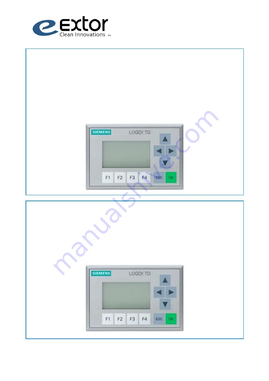
Cleaning after use begins when you press the 'F2' button to stop the suction machine. The 

suction machine continues to operate, with the suction inlet closed, during cleaning. It is 

possible to change the number of cleaning rounds from the display device or via the control 

centre logic display. The factory has pre-defined 10 cleaning rounds. 


CLEANING DURING USE 

The filter cleaning system has been designed to be fully automatic. The cleaning round begins 

when the pressure loss of the filters is high enough. Cleaning ends when the pressure limit set 

has been reached. It is possible to change the pressure limit thresholds for cleaning from the 

display device or from the control centre logic display. The factory has pre-defined pressure 

limits for filter cleaning for Cleaning on 3000 and for Cleaning off 2000 Pa.


Cleaning on 
 

3000 pas 

Cleaning off 
 

2000 pas 

Cleaning 
rounds 
 

10 


Summary of Contents for 4100R5

Page 1: ...OPERATION MAINTENANCE AND INSTALLATION EXTOR 4100R5...

Page 2: ...16 PRESSURIZED AIR CONNECTION 17 ELECTRICAL CONNECTION 18 STARTING AND STOPPING THE EQUIPMENT 19 SYSTEM CONTROL SETTINGS 20 EXTERNAL CONNECTIONS 23 A EMPTYING THE COLLECTING BIN WITH A CLOSING FLAP 2...

Page 3: ...ons of this manual You can ensure that the equipment functions properly by following the operation and maintenance instructions This product has been designed and manufactured to comply with the appro...

Page 4: ...a channel is connected to the suction inlet of the blower and the blower operates freely Efficiency category Static Efficiency grade 76 70 70 Year of manufacture 2014 Manufacturer Extor Oy Business I...

Page 5: ...42 EC on machinery and its enactment of national directive requirements SFS EN ISO 12100 comply low voltage directive 2006 95 EY SFS EN 60439 1 A1 2005 SFS EN 60439 3 A1 A2 2001 EN 60204 1 comply EMC...

Page 6: ...ce work should hold the key of the safety lock Use safety goggles a respirator and safety gloves when servicing operating or repairing the equipment Do not vacuum water or any other liquid Do not vacu...

Page 7: ...0 75 Pressurized air bar 4 5 Consumption of pressurized air l m 80 120 Pressurized air connection mm 8MM Cleaning of filters pneumatic Voltage V 24 Main filters m2 filtering material 3 x 15 PTFE EN 18...

Page 8: ...37 0 1000 2000 3000 4000 5000 6000 0 1000 2000 3000 4000 5000 6000 Air volume m3 h Vacuum Pa 60 HZ 50 HZ 60 HZ 0 1000 2000 3000 4000 5000 6000 0 1000 2000 3000 4000 5000 6000 Air volume m3 h Vacuum Pa...

Page 9: ...the filter unit tangentially The clean air can be used for suction blowing which makes the dust removal significantly more effective Some of the clean air is guided through the control filter back int...

Page 10: ...r back to the target room For proper functioning of the vacuum blowing system it is important to maintain sufficient underpressure in the cleaned room When using the system an adjusting damper adjusts...

Page 11: ...Pneumatic terminal M Pressure gauge N Pneumatic filter O Overfilling sensor P Drop through rotary feeder Q Set of cables remote control ACCEPTANCE INSPECTION B D C F G H I O J N M L A E P K Inspect th...

Page 12: ...en performing the installation remember the minimum space required for installation maintenance and operation The minimum space to be left around the equipment should conform to the rectangular area i...

Page 13: ...allation on a concrete base or a similar sufficiently solid base There must be at least 500 mm of free space above the suction unit Ambient temperature 0 40 C non condensing The equipment is designed...

Page 14: ...all the upper section to the stand Make sure that the alignment is correct 1 Attach slings to the four eyes Ensure uniform load distribution 4 Route cables to cable clamps x 12 WARNING Do not stand un...

Page 15: ...ocks 2 pcs and open the latches 6 pcs 2 Remove the service door 3 Take the new filter and place the loop located at the top of the filter into the holder 4 Install the filter and tighten the bolt 5 Ch...

Page 16: ...Page 16 37 360 1 Open the locking latches 4 pcs 2 Turn the outlet in the desired direction 3 Lock the latches ALIGNMENT OF THE BLOWING OUTLET Make sure that the gasket is in its place...

Page 17: ...ture may fall below 0 C Use dry oilfree compressed air Pressurized air that is unclean or has inferior pressure can weaken the efficiency of the cleaning system Water separator Compressed air supply i...

Page 18: ...n 50 lower Contact a professional electrician if it is necessary to change the rotation direction ELECTRICAL CONNECTION WARNING Risk of electric shock Disconnect the device from mains supply before ca...

Page 19: ...he electrical plug 4 Turn the main switch to position 1 5 The display panel will now display the main menu 6 F1 START F2 STOP F3 REMOTE F4 SETTINGS If you want to bypass cleaning after use press F4 af...

Page 20: ...During operation the operating time the actual pressure difference across the filter and the pressure difference and the clearing limits are shown on the display In addition an error message may also...

Page 21: ...cleaning rounds CLEANING DURING USE The filter cleaning system has been designed to be fully automatic The cleaning round begins when the pressure loss of the filters is high enough Cleaning ends when...

Page 22: ...the numerical value by using the arrow keys 7 Change all the values as desired and press OK Then press ESC 8 Changes have been saved Using the arrow keys you can scroll to move between and change valu...

Page 23: ...suction unit An error signal not visible on the display of the control unit is caused by the following events Motor protection Control logic is without current Power supply fault REMOTE OPERATION The...

Page 24: ...g F1 on the display device and holding for four seconds then you can detach the collecting bin After emptying the bin you must confirm the procedure by pressing F4 to open the seal AFTER THE CUTOFF VA...

Page 25: ...vacuum equipment the drop through rotary feeder discharges continuously into customer s own collecting vessel installed under the footing The drop through rotary feeder starts automatically when the...

Page 26: ...after you have finished cleaning IMPORTANT Remember to disconnect the cleaning hose always after cleaning When hose is connected there is no suction in duct MANUAL CLEANING ACCESSORY IMPORTANT Use the...

Page 27: ...s or at six month intervals Make sure that the cleaning system is functioning properly The opening and closing sound of cut off valves can be heard 9 times Impulse valves give pressure impacts in ever...

Page 28: ...o overheating or unusual noise Weekly Check and clean the ends of the rotor Lubricate bearings and seals Monthly Check the wear of bearing and bearing caps Replace with new ones if necessary Yearly Re...

Page 29: ...Turn the main switch to 0 position 2 Shut off compressed air supply and discharge pressure from the air lines of the equipment 3 Remove the door locking elements 2 pcs open the locking latches 6 pcs a...

Page 30: ...r 9 Install the filter and tighten the star knob 10 Check that all the filters are properly seated and the seal evenly compressed gap between the filter sheet and filter plate is 5 mm 11 Close the mai...

Page 31: ...the plug of the motor 3 Open the locking latches 4 pcs of the vacuum unit and remove the casing 4 Remove the control filter 5 Install the new control filter and reinstall the casing of the vacuum uni...

Page 32: ...pment and its parts on a wooden platform Tie the load safely before transferring Shield the equipment from the negative effects of weather Do not store in humid and salty conditions Taking into use af...

Page 33: ...essage about motor protection YES Contact the manufacturer NO Are you starting the suction machine remotely YES Make sure that the suction machine is in remote operating mode NO Make sure that the suc...

Page 34: ...er cleaning system operating YES Replace the filters NO Contact the manufacturer NO Does the motor rotate in the right direction YES Make sure that any sliding traps in the channel system are open and...

Page 35: ...o materials You can find the information about materials in the parts list 5 Deliver the sorted parts for recycling or disposal as required Materials of vacuum unit Steel parts collecting vessel frame...

Page 36: ...Page 36 37 SEAL COLLECTING BIN CABLE SET REMOTE CONTROL DROP THROUGH ROTARY FEEDER OVERFILLING SENSOR MANUAL CLEANING ACCESSORIES ACCESSORIES...

Page 37: ...ts c Fastening bolts d Filters e Fastening latches f Pressurized air connection g Electrical connection 3 Operation a Motor s direction of rotation b Cleaning system c Remote start d Seal of the colle...

Reviews: