background image

AvediaStream e2535/e3635 and e2655/e3655 Encoders V1.1 


28


Administrator’s Guide


Logging 

The encoder saves historical information about internal events within the device to its log file. 
This can be useful in troubleshooting problems with the device. It is also possible to send 
these log messages to a remote syslog server. 

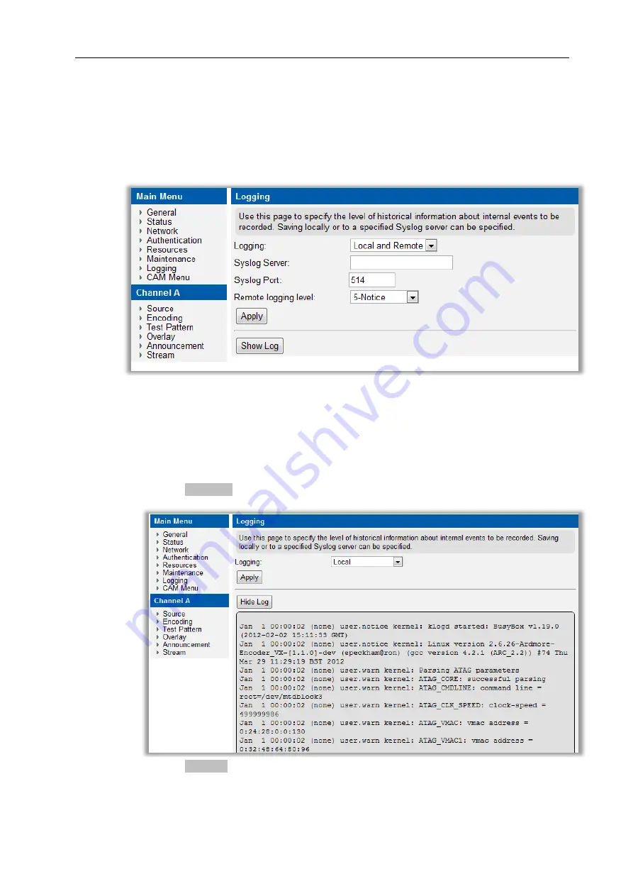
Logging is configured in the web interface 

Logging

 page as shown in Figure 13. 


Figure 13 Logging Page 

Local logging 

All log file information is automatically saved locally. 

To view the log file: 

1.  Click 

Logging

2.  Click the 

Show log

 button to display the log in a browser window. 


3.  Click the Hide Log button to close the log display. 


Summary of Contents for AvediaStream e2535

Page 1: ...AvediaStream e2635 55 and e3635 55 Encoders V1 1 Administrator s Guide...

Page 2: ...Player are U S registered trademarks of Microsoft Corporation Dolby and the double D symbol are trademarks of Dolby Laboratories HDMI the HDMI logo and High Definition Multimedia Interface are tradema...

Page 3: ...ace 19 AvediaServer Director 19 4 General Device Management 21 About The Encoder 21 Device Naming 22 Network Configuration 22 Authentication 24 Maintenance 25 Logging 28 5 Admin Interface 30 Admin int...

Page 4: ...ons 2 Keep these instructions 3 Heed all warnings 4 Follow all instructions 5 Do not use this apparatus near water 6 Clean only with dry cloth 7 Do not block any ventilation openings Install in accord...

Page 5: ...iceable parts inside any Exterity product To prevent electric shock or fire hazard do not remove cover Refer service to qualified service personnel WARNING For 230 240 volt operation be sure to use a...

Page 6: ...ssumes that readers are familiar with installing and configuring network based products Scope This edition of the manual refers to version 1 1 of firmware for the AvediaStream e2635 e2655 e3635 and 36...

Page 7: ...also referred to as TCP IP IP TOS The Type of Service TOS field is a six bit Differentiated Services Code Point DSCP field and a two bit Explicit Congestion Notification field MPEG A family of compre...

Page 8: ...Encoders V1 1 8 Administrator s Guide YPbPr A type of component analogue video signal consisting of a colourless component luminance combined with two colour carrying components chrominance This is c...

Page 9: ...dmin interface Chapter 4 General Device Management This chapter describes general configuration of the encoder For example IP address configuration and the firmware upgrade procedure are explained her...

Page 10: ...network For more information see the AvediaStream Installation Guide 3 Powering the Encoder Connect the encoder to a power source For more information see the AvediaStream Installation Guide 4 Configu...

Page 11: ...t system testing using common test patterns or add logos and text overlays to be displayed continuously or when no signals are present at the input of the encoder For more information refer to Test Pa...

Page 12: ...es the following interfaces over its edge connector to the chassis Ethernet interface 10 100Mbps Admin Interface Status LEDs Power supply The actual physical interfaces can be found on the chassis fro...

Page 13: ...support the following inputs and outputs Table 3 Encoder Rear Panel Interfaces Video Inputs e2635 e3635 e2655 e3655 HD Component SD Component HD AV RGBHV SD SDI SMPTE 259M HD SDI SMPTE 292M 3G SDI SMP...

Page 14: ...row 15 pin DE 15 plugs to connect to the RGBHV input Connect a YPbPr component source using the supplied VGA to phono adaptor female to connect to the RGBHV input Note High bandwidth Digital Content P...

Page 15: ...the S PDIF interface as the audio source Note The BNC interface is marked with ASI SDI as this interface is common to the SDI Encoder and ASI Gateway The interface is committed to SDI or ASI in the fa...

Page 16: ...page Caution Do not connect the output interface to any other output interface as this may damage the unit Audio Inputs Embedded SDI stereo audio stereo pair selectable from one of 8 pairs embedded w...

Page 17: ...ionality using the Web Management Interface The Web Management Interface supports Microsoft Internet Explorer and Mozilla Firefox You can display the Web Management Interface using the AvediaServer Di...

Page 18: ...menu Use this menu to navigate through the pages changing settings as required Click the Apply button on each page to save your changes Authentication You can control access to the web management int...

Page 19: ...ont panel or via telnet Figure 7 Admin Interface For more information on the use of the Admin Interface refer to Section 5 Admin Interface on page 30 AvediaServer Director The AvediaServer Director as...

Page 20: ...nterface and start the Director application Click the AvediaStream tab to list all streaming devices in the IPTV system 2 Select Encoder from the Device drop down list to display only encoders 3 Use t...

Page 21: ...the encoder from the General page in the web interface as shown in Figure 9 Much of this information is useful in identifying the software and hardware revisions in use in this module If contacting t...

Page 22: ...Click General 2 Enter a name and location as appropriate in the Name and Location fields 3 Click the Apply button Note The name and location can also be configured using the Name and Location actions...

Page 23: ...r can automatically negotiate any combination of 10 100 Mbps and half full duplex with an Ethernet switch It is also possible to disable auto negotiation resulting in a fixed setting of 100Mbps full d...

Page 24: ...fields 3 Click the Apply button SNMP With the SNMP agent enabled you can manage a subset of the encoder functions and configurations SNMP is used by applications such as the AvediaServer Director appl...

Page 25: ...cify the TFTP server IP address 1 Click Maintenance 2 Enter the IP address of the TFTP server in the TFTP Server field default 194 168 0 28 3 Click the Apply button Specifying the SNMP Trap Manager IP...

Page 26: ...erver is running at the IP address to be specified in step 4 2 Ensure that the following firmware file is hosted correctly in the root directory of the TFTP server encoder_vx bin 3 Click Maintenance 4...

Page 27: ...er is running 2 Click Maintenance 3 Ensure that the TFTP Server address is configured correctly see above 4 Enter a name for your configuration archive in the Export filename field 5 Click the Export...

Page 28: ...roblems with the device It is also possible to send these log messages to a remote syslog server Logging is configured in the web interface Logging page as shown in Figure 13 Figure 13 Logging Page Lo...

Page 29: ...er on the syslog server The default value is 514 5 Click the Logging level drop down list and select an option ranging from 0 Emergency to 7 Debug where 0 represents the least debug information and 7...

Page 30: ...to connect to the serial admin port Once connected log in using username admin and password as for the web interface default labrador Admin interface pages Main page When successfully logged in the m...

Page 31: ...assword for the serial and web interfaces Run a shell This allows the administrator to run a shell as admin Return to factory defaults This page allows the administrator to set all configurations to f...

Page 32: ...t the Input setups differ Configuration procedures are either individually described in the following sections or with the differences highlighted where appropriate Input configurations differ and are...

Page 33: ...input video signal This setting is not available when HDAV is selected The default is Auto To specify the HD video format 1 Click Source 2 With Component or RGBHV as the configured Video Input select...

Page 34: ...list 3 Click the Apply button Picture Control Picture Controls allow you to use the default brightness contrast saturation and hue settings of the video images in the streamed output from the encoder...

Page 35: ...he Audio Volume slider and drag it to the required level or click in the entry field and enter a value between 0 and 31 The default value is 31 no adjustment 4 Click the Apply button HDCP High bandwid...

Page 36: ...al can be presented at the SDI output of the AvediaStream e2655 and e3655 encoders using the Loop through function When Loop through is selected the SDI signal at the input is passed to the output wit...

Page 37: ...and Channel When Embedded is selected the module extracts the audio from the SDI stream Configure the Group and Channel settings to select the required audio from the 8 possible stereo pairs The defau...

Page 38: ...ing audio encoding The Encoding parameters are configured from the Encoding page on the web interface as shown in Figure 18 Figure 18 AvediaStream e3635 Encoding Page Default Settings MPEG Standard Th...

Page 39: ...bles you to reduce the bandwidth required in the output stream However this may affect the picture quality on fast action content The default is 50 Hz To specify the frame rate 1 Click Encoding 2 Clic...

Page 40: ...the Audio Standard drop down list to select Unchanged e2655 e3655 only MP2 or AAC 3 Click the Apply button Audio Bit Rate The bit rate can be set to values from 48kbps to 384kbps To specify the audio...

Page 41: ...o input signal is detected Test patterns can be useful during system commissioning when no other content is available or to highlight the lack of an input signal A selection of preset colours can be a...

Page 42: ...p down list 3 Click the Apply button Solid Colour If you have selected the Solid Colour test pattern option you can specify a preset or custom colour to be applied Custom colours are specified in RGB...

Page 43: ...ed in a single line with no wrap around The text is not scaled to suit the display resolution therefore higher resolution output encoding can display longer text strings The starting position of the t...

Page 44: ...rlay section Overlay Text entry field up to 64 characters If required click the Enable Double Wide Text and or Enable Double Height Text Enter the Start column and Start row values in the entry fields...

Page 45: ...iles 1 Click Resources 2 Ensure the files you want to use are located in the root folder of the TFTP server path and that the TFTP server address is correctly specified 3 Enter the filename you want t...

Page 46: ...Overlay 6 If no text is required select Off from the Overlay Mode 7 Click the Apply button Any text overlay is removed but the logo persists To delete logo files and return to the default logo 1 Clic...

Page 47: ...the last six digits of the encoder s MAC address The AvediaStream e2635 55 and e3655 are similar This can be changed as required To specify the channel name 1 Click Announcements 2 Enter the desired...

Page 48: ...list of group names as a comma separated list ensure there are no spaces in the list To remove the device from every group i e add the device to the all group 1 Click Announcements 2 Enter all in the...

Page 49: ...device To specify the transport protocol 1 Click Stream 2 Choose UDP or RTP from the Transport Protocol drop down list 3 Click the Apply button Destination Address By default the encoder sends its st...

Page 50: ...be set to any value between 0 and 255 to allow operation across different network topologies To specify the IP TTL 1 Click Stream 2 Enter a value between 0 and 255 in the IP TTL box 3 Click the Apply...

Page 51: ...o specify the stream on boot setting 1 Click Stream 2 Check or un check the Stream On Boot box as required 3 Click the Apply button IGMP Join Group The encoder by default uses IGMP to join the multica...

Page 52: ...rface Status page shown in Figure 26 Figure 26 AvediaStream e3635 Status Page Status Page Information The AvediaStream encoder Status page displays the following information with the output stream sta...

Page 53: ...r to Channel Announcements on page 47 for more information Video Format The Encoder displays the video encoding standard CODEC resolution frame rate and streamed bit rate of the output stream Audio Fo...

Page 54: ...the multicast address was assigned manually check it is unique Client cannot accept encoding type Update the client software or use a different client to view the stream If using PC client PC Firewall...

Page 55: ...DB 9 to RJ45 serial adaptor The female DB 9 connector should be plugged into the serial port on a PC A straight through network cable should be used between the RJ45 socket on the adaptor and the adm...

Page 56: ...as Hyperterminal this can be found on a standard Windows PC Set up the serial port with the following settings see example in Figure 30 Baud rate 115200 Data bits 8 Parity none Stop bits one Flow cont...

Page 57: ...V1 1 Administrator s Guide 57 APPENDIX B Support and Contact Information Technical Support for Exterity products is provided by authorised Systems Integrators and Resellers Please contact your System...

Reviews: