


23
The “Menu” page displays four features: Setpoint,
Component Activity, Dim LCD and Help. Tapping any of
these buttons will show dialog explaining the subject or
status of that button and display pictures.
“SETPOINTS”
The Setpoints page displays the Setpoints (the target
steam output of the humidifier) associated with the
unit. There are three different Setpoints, but only one
Setpoint is active at any given time. Each Setpoint is
accompanied by the current value of the Setpoint to the
right, and an indicator that represents its status.
The
Max Setpoint
is the user-specified Setpoint that is
active when no external controls or internal reduction is
taking place. The Max Setpoint is always modifiable via
the “Max Output Adjust” within the “Settings” menu.
2.
High Limit Humidistat
- Explains the status and shows
the current demand of the High Limit Humidistat. The
High Limit must call for a demand greater than 20% for
the humidifier to run. If needed, terminals ‘S’ and ‘GND’
on J17, on the main control board, can be wired together
to force a 100% demand.
The Control Humidistat, which provides the Control
Demand, is normally the humidistat located in the
room being humidified. It is either installed in the room
itself or the return air duct. The High Limit Humidistat,
which provides the High Limit Demand, is a safe-guard
humidistat, is usually set to a high level (80-90%), and
will shut down the humidifier if the humidity gets too
high in the supply duct. Without a High Limit Humidistat
properly installed the supply duct could reach a humidity
level where any steam entering the duct would readily
condense. Both Control Humidistats and High Limit
Humidistats are wired in the same way, only Control
Humidistats are wired to port J16 of the circuit board and
High Limit Humidistats are wired to port J17. Both ports
have the same number of pins and connection layout.
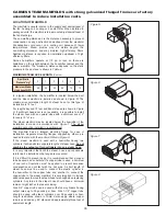
When using an on-off humidistat
, the percentage
should be either 100% or below 20%. In this case, the
control is either calling for full output or no output. On-Off
humidistats are dry contact switches. They will have two
wires; each connected to pins 2 and 4 (in no particular
order/polarity).
For a proportional humidistat
, any percentage value
is possible between 0% and 100%. In this case, the
humidifier can be modified to output any fraction of its
max output. If the proportional control falls to 20% or
below, the humidifier is shut off. The input signal of a
proportional humidistat must be 0-10V DC. Proportional
humidistats will have three wires, with ‘power’ going to
pin 1, ‘signal’ to pin 3 and ‘ground’ to pin 4.
In lieu of a
humidistat, a DDC signal
from a building management
system may also be used. Here, the ‘signal’ should be
connected to pin 3, and ‘ground’ to pin 4. In this case,
‘power’ can be ignored. A DDC signal must be of a
0-10V signal by adding a 470 ohm resistor between the
‘signal’ (pin 3) and ‘ground’ (pin 4).
3.
Air Flow
- Explains the status of the Air Flow switch.
The Air Flow switch must sense proper air flow in order
for the humidifier to activate. Insufficient air flow or
an improperly installed air flow switch will cause the
indicator to change to a red “
X
” and the unit will not
operate. If needed, terminals ‘AFS’ and ‘GND’ on J18,
on the main control board, can be wired together to force
activation of the switch.
4.
Door Interlock
- Explains the status of the Door Interlock
switch. The Door Interlock needs to be engaged for the
unit to operate. This can be accomplished by either
locking the door shut or pulling out the plunger for
temporary operation while servicing the unit.
MENU


