background image

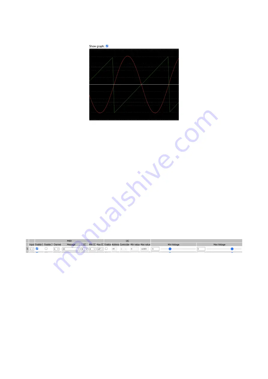
Graph View

The 'Show graph' checkbox enables a graph view of the module's inputs.

Each input is shown in a different colour – red, green, blue, cyan, magenta, yellow, orange, and 
white for inputs 1 to 8 respectively.

Configuration Wizard

The 'Configuration Wizard' lets you quickly set up the entire module using common configuration 
choices – for example, all inputs generating MIDI CCs, or all inputs used as CV/gate pairs to 
generate MIDI notes.
It should be fairly self-explanatory once you understand the configuration options below.
There is one 'wizard' per line. Choose your settings and click the 'GO' button.

Continuous Generators

Here is where you set up the generation of 'continuous' message streams, where typically a new 
message is generated whenever the input voltage changes. Often these will be MIDI CCs or I2C 
controllers, though other options are available.

There are sixteen generators available. In the default and wizard-generated configurations the first 
eight generators are used, in one-to-one correspondence with the eight inputs, but this relationship is 
not fixed. If you wanted, you could generate 16 different CCs from one input.
Each row in the generator table is divided into four sections – input, MIDI, I2C, and voltages.
The input section has one control, a drop-down menu to select the module input that is used.
The MIDI section begins with 'Enable 1' and 'Enable 2', to enable the generation of messages on 
MIDI ports 1 and 2 respectively. Next come menus for the MIDI channel (1-16) and message. The 
message options are CC, Program Change, Channel Pressure (aka aftertouch), Poly Pressure (aka 
polyphonic aftertouch), and Pitch Bend. For CC and Poly Pressure messages, the CC menu allows 
you to choose the CC number or note number for the messages. The 'Min CC' and 'Max CC' menus 
allow you to set the minimum and maximum controller values that will be sent, corresponding to 
the minimum and maximum voltages. (These are not used for Pitch Bend messages, which always 

Page 9

Summary of Contents for CVM-8

Page 1: ...CVM 8 Firmware v1 0 User Manual Page 1 ...

Page 2: ...ed or copied only in accordance with the terms of such licence The content of this manual is furnished for informational use only is subject to change without notice and should not be construed as a commitment by Expert Sleepers Ltd Expert Sleepers Ltd assumes no responsibility or liability for any errors or inaccuracies that may appear in this document Page 2 ...

Page 3: ...6H Request configuration names 14 27H Request DIP switches 14 28H Request settings 14 30H Update CC generator 14 31H Update configuration name 14 32H Update note generator 14 33H Update settings 14 34H Reset 14 40H Reset configuration 15 41H Load configuration 15 42H Save configuration 15 Sent SysEx messages 15 10H Configuration dump 15 11H Configuration names 15 12H Settings 15 32H Message 15 33H...

Page 4: ...he module has no user interface of its own it makes most sense to describe it in terms of the functionality offered by the configuration tool documented below Please read on Installation House the module in a Eurorack case of your choosing The power connector is Doepfer standard1 If using the power cable supplied with the module the red edge of the cable is closest to the bottom edge of the PCB an...

Page 5: ...MIDI 1 RX MIDI 2 RX I2C RX I2C TX MIDI 2 TX MIDI 1 TX MIDI Connections The CVM 8 has two independent MIDI ports each consisting of the traditional in out and thru They are exposed on the header strip across the top of the PCB marked X1 Pin numbers refer to the 5 pin DIN socket as in the MIDI specification2 All the necessary electronics are part of the module all that is required to use these as MI...

Page 6: ...ommunication currently supported by a handful of modules from various manufacturers including the Malekko Varigate 8 4 Macro Machines Storage Strip5 and the Make Noise Tempi6 René 27 Expert Sleepers modules which use the Select Bus include the disting mk4 and disting EX The CVM 8 can only transmit on the Select Bus it cannot receive So it is a leader only in the parlance of some Select Bus devices...

Page 7: ... firmware download page8 A standalone version is provided for macOS and Windows as well as a platform independent browser based version This last uses the Web MIDI API which at the time of writing will work only in browsers based on Google s Chromium which includes Chrome All is well if the tool shows Web MIDI status OK If it shows Web MIDI status No MIDI support in your browser then you need to u...

Page 8: ... the last SysEx message received by the tool and in the case of the Message SysEx message the actual message as plain text Raw Inputs Below the log messages is the raw inputs area Untick the check box if you don t want this area visible Three values are shown for each input The top row shows the raw ADC code coming from the hardware The centre row shows the input as a voltage The bottom row shows ...

Page 9: ...tors available In the default and wizard generated configurations the first eight generators are used in one to one correspondence with the eight inputs but this relationship is not fixed If you wanted you could generate 16 different CCs from one input Each row in the generator table is divided into four sections input MIDI I2C and voltages The input section has one control a drop down menu to sel...

Page 10: ...le inputs to use for pitch gate and velocity Any of these can be None If the pitch input is None the value from the Fixed Pitch field is used as the pitch If the velocity input is None the value from the Fixed Velocity field is used as the note on velocity If the gate input is None no new notes will be generated but a note off message will be generated if a note on message was previously sent The ...

Page 11: ...ould cause this slot to be loaded at power on Settings Unlike the configuration which is volatile until saved settings apply globally and are saved immediately There is currently just one setting which is the module s I2C address when operating as a follower The default value for this is 50 0x32 Finally at the very bottom of the configuration tool is the Full Reset button This resets the settings ...

Page 12: ... fixed velocity 127 using CV gate inputs 7 8 0V note 48 gate offset 0 5ms 1 0 1 0 7 MIDI fixed notes Eight MIDI note generators using MIDI channel 1 on both MIDI ports The eight generators use inputs 1 to 8 and generate notes 48 55 with a fixed velocity of 127 Gate offset 0 5ms 0 1 1 0 8 MIDI fixed notes vel Four MIDI note generators using MIDI channel 1 on both MIDI ports Gate and velocity inputs...

Page 13: ... a 16 bit quantity top 2 bits middle 7 bits low 7 bits Similarly a 5 byte format is used to represent a 32 bit quantity top 4 bits next 7 bits next 7 bits next 7 bits low 7 bits Received SysEx messages 08H Reboot F0 00 21 27 58 08 F7 This causes the CVM 8 to reboot Used by the configuration tool to enter bootloader mode 22H Request version string F0 00 21 27 58 22 F7 This causes the CVM 8 to respo...

Page 14: ... 32H below 28H Request settings F0 00 21 27 58 28 F7 This causes the CVM 8 to respond with a SysEx message containing the current settings using message 12H below 30H Update CC generator F0 00 21 27 58 30 version generator index data F7 Used to update a single CC generator 31H Update configuration name F0 00 21 27 58 31 ASCII string F7 Used to set the current configuration name 32H Update note gen...

Page 15: ...ation 11H Configuration names F0 00 21 27 58 11 number of configurations list of NULL terminated ASCII strings F7 Contains the names of the CVM 8 s configurations stored in flash 12H Settings F0 00 21 27 58 12 settings data F7 Contains the CVM 8 s settings 32H Message F0 00 21 27 58 32 NULL terminated ASCII string F7 This message is used to transmit any human readable string 33H Raw inputs F0 00 2...

Page 16: ...value Y address 0x11 controller number value MSB value LSB set voice pitch for note id address 0x54 note id pitch MSB pitch LSB note on for specified note id address 0x55 note id velocity MSB velocity LSB note off for specified note id address 0x56 note id Received I2C messages get raw ADC code 16 bit address 0x00 input number 0 7 returns 2 bytes get input voltage 16384 10V address 0x01 input numb...

Page 17: ...der mode the module s I2C RX TX LEDs the bottom two will flash alternately about once a second Use the Choose file button to browse for the firmware file downloaded previously Click the Install Firmware button Wait for the progress bar to reach the end Check the final message in the log window It should be Bootloader reports completion Power cycle the module turn it off and on Reload the config to...

Reviews: