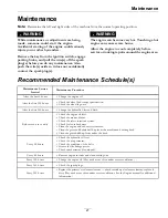

Maintenance
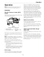
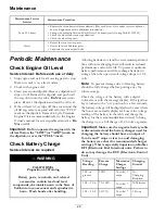
Voltage
Reading
Percent
Charge
Maximum
Charger
Settings
Charging
Interval
12.0–12.2
25–50%
14.4 volts/4
amps
2 Hours
11.7–12.0
0–25%
14.4 volts/4
amps
3 Hours
11.7 or less
0%
14.4 volts/2
amps
6 Hours or
More
Important:
For Kohler EFI units: Unplug the
harness from the ECU before performing any
welding on the equipment.
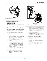
Recommended Jump
Starting Procedure
Service Interval: As required
1. Check the weak battery for terminal corrosion
(white, green, or blue “snow”), it must be cleaned
off prior to jump starting. Clean and tighten
connections as necessary.
CAUTION
Corrosion or loose connections can cause
unwanted electrical voltage spikes at anytime
during the jump starting procedure.
Do Not attempt to jump start with loose or
corroded battery terminals or damage to the
engine or EFI may occur.
DANGER
Jump starting a weak battery that is cracked,
frozen, has low electrolyte level, or an
open/shorted battery cell, can cause an
explosion resulting in serious personal injury.
Do Not jump start a weak battery if these
conditions exist.
2. Make sure the booster is a good and fully charged
lead acid battery at 12.6 volts or greater. Use
properly sized jumper cables (4 to 6 AWG) with
short lengths to reduce voltage drop between
systems. Make sure the cables are color coded or
labeled for the correct polarity.
CAUTION
Connecting the jumper cables incorrectly
(wrong polarity) can immediately damage the
electrical and/or EFI system.
Be certain of battery terminal polarity and
jumper cable polarity when hooking up
batteries.
Note:
The following instructions are adapted
from the SAE J1494 Rev. Dec. 2001 – Battery
Booster Cables – Surface Vehicle Recommended
Practice (SAE – Society of Automotive
Engineers).
WARNING
Batteries contain acid and produce explosive
gases.
•
Shield the eyes and face from the batteries
at all times.
•
Do Not lean over the batteries.
Note:
Be sure the vent caps are tight and level.
Place a damp cloth, if available, over any vent
caps on both batteries. Be sure the vehicles do
not touch and that both electrical systems are
off and at the same rated system voltage. These
instructions are for negative ground systems only.
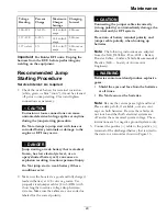
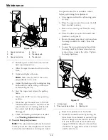
3. Connect the positive (+) cable to the positive (+)
terminal of the discharged battery that is wired to
the starter or solenoid as shown in Figure 13.
29
Summary of Contents for VANTAGE X Series
Page 1: ...VANTAGE X SERIES For Serial Nos 315 000 000 Higher Part No 4502 224 Rev A ...
Page 51: ...Schematics Schematics Electrical Diagram All Units Except Kohler EFI 51 ...
Page 52: ...Schematics Electrical Diagram Kohler EFI 52 ...
Page 53: ...Schematics Electrical Schematic All Units Except Kohler EFI 53 ...
Page 54: ...Schematics Electrical Schematic Kohler EFI 54 ...
Page 55: ...Schematics Hydraulic Diagram 55 ...
Page 57: ...Service Record Date Description of Work Done Service Done By 57 ...
Page 58: ...58 ...


