2. Product Overview
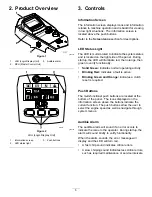
g030387
Figure 1
1.
LDU (Logic Display Unit)
3.
Audible alarm
2.
MCU (Master Control Unit)
g030160
Figure 2
LDU (Logic Display Unit)
1.
Information screen
3.
Push buttons
2.
LED status light
3. Controls
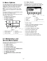
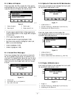
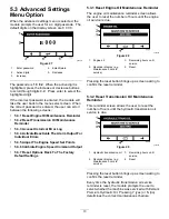
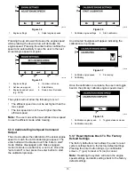
Information Screen
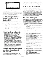
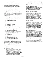
The information screen displays icons and information
relative to machine operation and is backlit for viewing
in low light situations. The information screen is
located above the push buttons.
Refer to the
Screen Icons
section for descriptions.
LED Status Light
The LED is multi-colored to indicate the system status
and is located on the right side of the panel. During
startup, the LED will illuminate red, then orange, then
green to verify functionality.
•
Solid Green:
indicates normal operating activity.
•
Blinking Red:
indicates a fault is active.
•
Blinking Green and Orange:
indicates a clutch
reset is required.
Push Buttons
The multi-functional push buttons are located at the
bottom of the panel. The icons displayed on the
information screen above the buttons indicate the
current function. The push buttons allow the user to
select the engine speed as well as navigate through
system menus.
Audible Alarm
The audible alarm will sound if an error occurs to
indicate the issue to the operator. During startup, the
alarm will sound briefly to verify functionality.
When the alarm sounds, the error message will
display and the LED will turn red.
•
A fast chirp sound indicates critical errors.
•
A slow chirping sound indicates less critical errors,
such as required maintenance or service intervals.
5


