


Page 10 of 13
109-4195 Rev. A
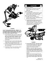
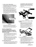
Align Dimple Here
mounting pin. The mount pin can be installed in
two positions. For 60” decks, SN 599,999 and
lower, the pin should be installed as far away from
the bumper end as possible. For all 72” decks
and 60” and 66” decks SN 600,000 and higher,
the pin should be installed close to the bumper
end (See Figure 13).
FIGURE 13
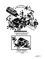
28. Install the belt (Item 13) onto the blower by
working it around the impeller sheave.
FIGURE 14
All units
:
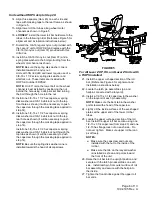
29. Mount the blower on the deck by sliding the
mounting pin into the tube at the rear right corner
of the deck. Swing the blower closed. Adjust the
position of the front pin to engage the slot in the
front of the deck. Use the latch to lock the blower
in this position. Adjust the tension on the latch to
hold the blower up to the deck, yet allow for
release by hand.
30. Pull the spring loaded idler back and slip the
belt over the top deck spindle sheave.
31. Install the plastic belt cover (Item 10). On 60”
and 66” units the outside end of the cover is
slotted and can slip between the two washers
assembled in step 26. The plastic knob does
not need to be removed. On 72” units the
cover has a hole, and the plastic knob must
be installed after the cover has been
positioned.
On Units SN 600,000 and Higher with Triton
decks
:
32. Adjust dog leg baffle to match Ultra Vac
blower intake opening. Adjusting too wide
may allow objects to be thrown from under the
mower deck at high speed. Adjusting too
narrow may cause plugging issues.
WARNING
POTENTIAL HAZARD
♦
If the blower intake opening is not correct it
will allow objects to be thrown in operator’s or
bystander’s direction. Also, contact with blade
could occur.
WHAT CAN HAPPEN
♦
Thrown objects or blade contact can cause
serious injury or kill you or bystanders.
HOW TO AVOID THE HAZARD
♦
Adjust dog leg baffle to match intake opening.
Assemble the Tubes
1. Slip upper and lower tubes together.
2. Insert upper tube into hopper seal – push in
then pull out so that seal is extended outward.
Align dimple on upper tube with end of hopper
seal and position vertically between the two
screws as shown in Figure 15.
FIGURE 15


