


Page 7 of 13
109-4195 Rev. A
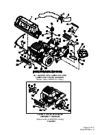
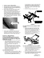
FIGURE 6
All units
:
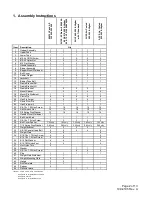
28. Tighten all hardware that attaches the Ultra Vac
mount to the machine frame. Start with the
screws that hold the mount weldment to the rear
of the unit and work forward.
All units with a ROPS installed:
29. Torque all lower roll bar hardware attached to the
machine frame to 30-35 ft-lbs (41-47 N-m).
Lazer Z units with SN 352,000 – 509,999:
30. Reinstall the rear wheels and lower the unit from
the jack stands.
All Lazer Z XP, All Lazer Z XS, and Lazer Z
SN 510,000 and Higher:
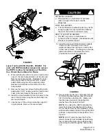
31. Attach the handle assembly (Item 7) onto frame
bracket (Item 16) using 3/8-16 x 1.00 screws
(Item 23), 3/8 spring disk washers (Item 25) and
3/8-16 whizlock nuts (Item 24). Make sure that
the raised portion of the spring disk washer faces
the head of the screw. (See Figure 7)
Lazer Z units with SN 352,000 – 509,999 only:
32. Remove the E-clip and handle from the handle
assembly (Item 7). Discard the mount that came
with the handle assembly. Install the handle and
E-clip onto the handle mount (Item 26) that came
in the completing kit.
33. Mount the handle assembly (Item 7) onto left
hand frame bracket (Item 15) using 3/8-16 x 1.00
screws (Item 23), 3/8 spring disk washers (Item
25) and 3/8-16 whizlock nuts (Item 24). Make
sure that the raised portion of the spring disk
washer faces the head of the bolt.
(See Figure 7)
FIGURE 7
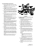
All units
:
34. Apply a light coat of grease to the front and
rear of the upper tube of the mount weldment.
Install the hopper assembly (Item 1) onto the
mount by slipping the hook portion over the
top mounting tube of the mount weldment.
Secure the assembly to the mount using the
clevis pins (Item 19) and hairpins (Item 20).


