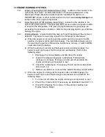
background image

- 32 -

e)

Insert Caster Spacer.

f)

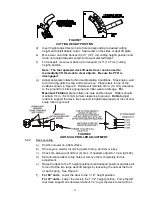
With open end of wheel up, fill area inside wheel around caster spacer with
NGLI grade #2 multi-purpose gun grease.

g)

Insert the second (1) bearing, (1) new seal, and (1) bearing spacer.

h)

Put wheel and tire assembly on the unit and adjust by tightening the nyloc
nut until wheel will not turn freely.  Back nut off 1/6 of a turn so the wheel
will just turn with a slight amount of drag.

IMPORTANT

:  To prevent seal and bearing damage, check the bearing

adjustment often.  Spin the caster tire.  The tire should not spin freely (more
than 1 or 2 revolutions) or have any side play.  If the wheel spins freely
adjust per step h).

5.1.17

Lubricate brake handle pivot:

Service Interval: 160 hrs.

a) Stop engine, wait for all moving parts to stop, and remove key.

b) Lubricate bronze bushings on brake handle pivot with a spray type lubricant

or light oil.

5.1.18

Lubricate brake rod bushings:

Service Interval: 160 hrs.

a)

Stop engine, wait for all moving parts to stop, and remove key.

b)

Lubricate bronze bushings on each end of brake rod shaft with a spray type
lubricant or a light oil (bushings are located to the inside of the flange
bearings).

5.1.19

Lubricate motion control bronze bushings:

Service Interval: 160 hrs.

a)

Stop engine, wait for all moving parts to stop, and remove key.

b)

Tilt seat up.

c)

Lubricate bronze bushings on flange bearings securing the motion control
arm shafts with a light oil or a spray type lubricant.

5.1.20

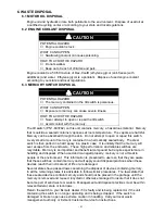
Check spark plugs 

(31 HP Daihatsu Gas units only)

:

Service Interval: Yearly.

a) Remove spark plugs, check condition and reset gaps, or replace with new

plugs.  See Engine Owners Manual.

5.1.21

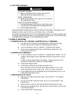
Drain fuel filter 

(27 HP Daihatsu Diesel units only)

:

Service Interval:  

When Water in Fuel warning light is “ON”

a) Stop engine, wait for all moving parts to stop, and remove key.

b) Place a drain pan under the fuel filter and loosen the drain plug

approximately 1 turn.

c) Water should drain.

d) When fuel begins to flow from the filter, tighten the drain plug.

e) Prime the fuel system (See Section 5.1.24).

f)

Start engine.  Make sure warning light goes out.  Check for leaks.

IMPORTANT: Water or other contaminants in fuel can 

severely damage

 fuel

pump and/or the other engine components.

5.1.22

Replace fuel filter:

Service Interval:  31 HP Daihatsu Gas units – 600 hrs.

27 HP Daihatsu Diesel units – 800 hrs.

Summary of Contents for Laser Z XP

Page 1: ...oduct has been carefully designed and manufactured to give you a maximum amount of dependability and years of trouble free operation If additional information is needed or should you require trained mechanic service contact your authorized Exmark equipment dealer or distributor If you need to order replacement parts from your dealer always give the model number and serial number of your mower as w...

Page 2: ...apors has caused cancer in laboratory animals WHAT CAN HAPPEN Failure to use caution may cause serious injury or illness HOW TO AVOID THE HAZARD Avoid prolonged breathing of vapors Keep face away from nozzle and gas tank container opening Keep away from eyes and skin Never siphon by mouth IMPORTANT When the mower is used or operated on any California forest brush or grass covered land a working sp...

Page 3: ...bmitting the Exmark Parts Plus order to Exmark by 3 00 p m central time the Distributor pays for the part and freight 3 Exmark being unable to ship the part and the Exmark parts order is received by 3 00 p m central time Exmark pays for the part and freight 4 If the part does not arrive overnight due to the shipper UPS the shipper pays for the freight and Exmark pays for the part The following res...

Page 4: ...wer maintain its maximum efficiency and promote safe operation If additional information is needed or should you require trained mechanic service contact your authorized Exmark equipment dealer or distributor All Exmark equipment dealers and distributors are kept informed of the latest methods of servicing and are equipped to provide prompt and efficient service in the field or at their service st...

Page 5: ...13 3 2 Service Battery 13 15 3 3 Install Drive Wheels 15 3 4 Check Tire Pressure 15 3 5 Install Seat 15 3 6 Install Foot Lift Assist 15 3 7 Install Motion Control Levers 15 16 3 8 Position Discharge Chute 16 3 9 Service Engine 16 3 10 Service Engine Coolant 16 17 3 11 Service Hydraulic Oil 17 4 OPERATION INSTRUCTIONS 4 1 Controls 17 20 4 2 Pre Start 20 4 3 Mowing 21 22 4 4 Transporting 22 23 5 MAI...

Page 6: ... the owner s responsibility to explain this material to them 1 2 3 Do not allow operation of this machine by untrained personnel Never allow children teenagers or people unfamiliar with these instructions to use the mower Local regulations may restrict the age of the operator 1 2 4 Avoid mowing while people especially children or pets are nearby Keep in mind that the operator or user is responsibl...

Page 7: ... WHAT CAN HAPPEN A fire or explosion from gasoline or diesel fuel can burn you others and cause property damage HOW TO AVOID THE HAZARD DO NOT smoke while refueling and stay away from an open flame or where fuel fumes may be ignited by spark Refuel only outdoors Store fuel in an approved container and keep it out of the reach of children Add fuel before starting the engine Never remove the cap of ...

Page 8: ...e then refuel such equipment on a truck or trailer from a portable container rather than from a gasoline dispenser nozzle If a gasoline dispenser nozzle must be used keep the nozzle in contact with the rim of the fuel tank or container opening at all times until fueling is complete WARNING POTENTIAL HAZARD Gasoline vapor can collect inside enclosed trailers and may be ignited by electrical sparks ...

Page 9: ...lacerations HOW TO AVOID THE HAZARD Do not operate the machine without guards shields and safety devices in place and working Keep hands feet hair jewelry or clothing away from rotating parts 1 4 1 Give complete undivided attention to the job at hand 1 4 2 Mow only in daylight or good artificial light keeping away from holes and hidden hazards NEVER carry passengers DO NOT operate the mower when c...

Page 10: ...n Keep on running at idle for a short time approximately one minute then stop the engine NOTE For 31 HP Daihatsu Gas Units Do not move the choke to the ON position to stop the engine Backfire or engine damage may occur 1 4 14 The fuel system is provided with a shut off valve Shut off the fuel When the machine will not be used for a few days During transport to and from the job When parked inside a...

Page 11: ...ces are present 1 5 8 Maximum mowing results and safety can only be achieved if the mower is properly maintained and operated correctly 1 5 9 Check all bolts frequently to maintain proper tightness 1 5 10 Keep all guards shields and all safety devices in place and in safe working condition 1 5 11 Frequently check for worn or deteriorating components that could create a hazard 1 5 12 All replacemen...

Page 12: ...ust be replaced if they are missing or illegible 1 6 3 When new components are installed be sure that current safety signs are affixed to the replaced components 1 6 4 New safety signs may be obtained from your authorized Exmark equipment dealer or distributor or from Exmark Mfg Co Inc 1 6 5 Safety signs may be affixed by peeling off the backing to expose the adhesive surface Apply only to a clean...

Page 13: ...Mower Deck PART NO 103 2076 LOCATION Top of Radiator Trim Plate LH RH Sides PART NO 1 643401 LOCATION On Tilt Switch PART NO 103 1077 LOCATION Top LH Side of Mower Deck next to Stiffener PART NO 103 1593 LOCATION Bottom Side of Floorpan PART NO 103 1596 LOCATION Center Inside of the Rear Bumper 27 HP Daihatsu Diesel Units Only PART NO 103 1636 LOCATION Top of Fuel Tanks ...

Page 14: ...k PART NO 98 5954 LOCATION Under LH and RH Belt Shields Radiator Fan Pump Idler Arm PART NO 103 0368 LOCATION Rubber Heat Shield Flap behind Seat PART NO 1 303508 LOCATION RH Side on Top Rear of Mower Deck PART NO 1 643253 LOCATION LH and RH Sides of Radiator Mount Plate 27 HP Daihatsu Diesel Units Only PART NO 103 1979 LOCATION LH Side of Console PART NO 1 513746 LOCATION Rear RH Side of Engine D...

Page 15: ...k Under Floor Pan PART NO 1 633922 LOCATION Front Center on Top of Mower Deck PART NO 1 523552 LOCATION Top of Hydraulic Reservoir PART NO 103 1365 LOCATION Right of Center on Front of Console 27 HP Daihatsu Diesel Units Only PART NO 103 1505 LOCATION Left of Center on Front of Console 31 HP Daihatsu Gas Units Only PART NO 103 1506 LOCATION Left of Center on Front of Console PART NO 103 0245 LOCAT...

Page 16: ...k to start engine It is not necessary for the operator to be in the seat to start the engine Operator must be in seat when PTO is engaged brake is disengaged or motion control levers are moved in or engine will stop Engine will stop if either the left the right or both levers are moved from neutral lock position while brake is engaged 2 4 8 Tilt Switch Shuts off the engine when the unit is tilted ...

Page 17: ...ydraulic Filter Replaceable cartridge type P N 103 2146 25 microns No bypass 2 8 6 Speeds 0 11 0 mph 17 7 km hr forward 0 7 0 mph 11 3 km hr reverse 2 8 7 Drive wheel release valves allow machine to be moved when engine is not running 2 9 TIRES AND WHEELS 2 9 1 Tires Drive Front Caster Qty 2 2 Ply 4 4 Infl 13 psi 90 kPa 13 psi 90 kPa Size 24 x 12 0 12 13 x 6 50 6 Tread Turf Master Smooth 2 10 CUTT...

Page 18: ...r tire to center of drive tire w 60 Decks 54 0 in 137 2 cm w 72 Deck 56 8 in 144 3 cm 2 11 6 Curb Weight 27 HP Daihatsu Diesel w 60 Deck 1565 lbs 709 kg w 72 Deck 1583 lbs 718 kg 31 HP Daihatsu Gas w 60 Deck 1541 lbs 699 kg w 72 Deck 1542 lbs 699 kg 2 12 TORQUE REQUIREMENTS Bolt Location Torque Cutter Housing Spindle Nut 75 80 ft lbs 102 109 N m Blade Mounting Bolt 115 120 ft lbs 156 163 N m Engin...

Page 19: ...g Interval 12 6 or greater 100 16 volts 7 amps No Charging Required 12 4 12 6 75 100 16 volts 7 amps 30 Minutes 12 2 12 4 50 75 16 volts 7 amps 1 Hour 12 0 12 2 25 50 14 4 volts 4 amps 2 Hours 11 7 12 0 0 25 14 4 volts 4 amps 3 Hours 11 7 or less 0 14 4 volts 2 amps 6 Hours or More CAUTION POTENTIAL HAZARD If the ignition is in the ON position there is potential for sparks and engagement of compon...

Page 20: ...and remove the two 2 3 8 x1 bolts and spring disk washers which attach the motion control levers to the control arm shafts for shipping and the two 2 3 8 x 1 bolts and spring disk washers which are screwed into the control arm shafts a Install the left motion control lever onto the control arm shaft See Figure 2 on the left side of the console Place the lever with the mounting plate towards the re...

Page 21: ...of the cooling system CAUTION POTENTIAL HAZARD Engine coolant is toxic WHAT CAN HAPPEN Swallowing coolant can cause poisoning HOW TO AVOID THE HAZARD Do not swallow Keep out of reach of children and pets With machine on level surface and with cool engine remove radiator cap under hood and add a 50 50 mix of water and Dex Cool extended life coolant until liquid level is as high as possible without ...

Page 22: ...ystem is in the neutral position With levers moved out in the T slot the drive system is in the neutral lock position See Figure 4 FIGURE 4 MOTION CONTROL POSITIONS By moving both levers an equal amount forward or back from the neutral position the machine can be caused to move forward or backward in a straight line Movement of the left lever forward will cause the left drive wheel to rotate in a ...

Page 23: ...ke engaged when transporting 4 1 7 Ignition Switch Located on the lower center of console The ignition switch is used to start and stop the engine The switch has three positions OFF ON and START Insert the key into switch and rotate clockwise to the ON position Rotate clockwise to the next position to engage the starter key must be held against spring pressure in this position NOTE On 27 HP Daihat...

Page 24: ...el tank The coolant temperature gauge monitors the temperature of the engine coolant The engine will overheat if the coolant temperature becomes too high 4 1 12 Voltmeter Located next to the Coolant Temperature Gauge at the front of the right fuel tank The voltmeter measures the voltage output of the alternator Both high and low voltages will potentially damage the battery 4 1 13 Water in Fuel Lig...

Page 25: ...r s Manual For 27 HP Daihatsu Diesel Units For best results use only clean fresh diesel fuel with a cetane rating of 40 higher NOTE Do not use kerosene or gasoline instead of diesel fuel Failure to observe this caution will damage the engine For All Units DO NOT add oil to gasoline DO NOT overfill fuel tank Never fill the fuel tank so that the fuel level rises above a level that is 1 2 below the b...

Page 26: ...ons are clear of the mower deck and discharge area before engaging PTO IMPORTANT Operator must be in seat before the PTO can be engaged Set throttle to midway position Pull outward on the switch to the ROTATE position Accelerate to full throttle to begin mowing 4 3 4 Stopping PTO Set throttle to the idle position Push in on the switch to the STOP position stopping the cutting blades 4 3 5 Stopping...

Page 27: ... public street or roadway WARNING POTENTIAL HAZARD Loading a unit on a trailer or truck increases the possibility of backward tip over WHAT CAN HAPPEN Backward tip over of the unit could cause serious injury or death HOW TO AVOID THE HAZARD Use extreme caution when operating a unit on a ramp Use only a single full width ramp DO NOT use individual ramps for each side of the unit If individual ramps...

Page 28: ...gh individual ramps to simulate a full width continuous ramp Ramp should be long enough so that the angles between the ramp and the ground and the ramp and the trailer or truck do not exceed 15 A steeper angle may cause mower deck components to get caught as the unit moves from ramp to trailer or truck Steeper angles may also cause the unit to tip backward If loading on or near a slope position th...

Page 29: ...IAL HAZARD Engine coolant is hot and pressurized Radiator and surrounding parts are hot WHAT CAN HAPPEN Spray or steam from hot pressurized liquid in the engine cooling system or touching a hot radiator may cause severe burns HOW TO AVOID THE HAZARD Allow the engine to cool completely before removing the radiator cap or servicing any component of the cooling system CAUTION POTENTIAL HAZARD Engine ...

Page 30: ...creen in engine cover Rotate engine cover forward and wipe debris from radiator core as required Inspect seals in engine cover and replace as necessary 5 1 5 Clean grass build up under deck Service Interval Daily a Stop engine wait for all moving parts to stop and remove key b Raise deck to the transport 5 cutting height position Lift the front of unit and support unit using jack stands or equival...

Page 31: ... threads of the bolt or spindle before assembly Torque the blade bolt to 115 120 ft lbs 156 13 N m FIGURE 5 BLADE BOLT INSTALLATION 5 1 7 Check safety interlock system Service Interval Daily a Check starting circuit Starter should crank with parking brake engaged PTO disengaged and motion control levers moved out in the neutral lock position The operator does not need to be in the seat to start th...

Page 32: ...ait for all moving parts to stop and remove key b Visually inspect machine for any loose hardware or any other possible problem Tighten hardware or correct the problem before operating 5 1 9 Service air cleaner Canister type 2 stage cleaner Service Intervals First service interval 50 hrs Normal service interval 100 hrs Replacement interval 600 hrs more often under heavy load or high temperatures a...

Page 33: ...inutes then check the oil level If required add oil to bring level to the FULL mark on the dipstick DO NOT overfill k Check for leaks including around the oil filter 5 1 11 Change engine coolant Service Interval 4 years 4000 hours Dex Cool extended life coolant orange color It is recommended to service at whichever interval happens first a Stop engine wait for all moving parts to stop and remove k...

Page 34: ...engine as required to bring the level up to the indicator line on the bottle WARNING POTENTIAL HAZARD Engine compartment contains open belt drives and fans Rotating components can cause injury WHAT CAN HAPPEN Fingers hands loose clothing or jewelry can get caught by the rotating fan and drive shaft HOW TO AVOID THE HAZARD Do not operate machine without the covers in place Keep fingers hands and cl...

Page 35: ...re about 75 F 24 C fill only to the COLD level WARNING POTENTIAL HAZARD Hydraulic fluid escaping under pressure can penetrate skin and cause injury WHAT CAN HAPPEN Fluid accidentally injected into the skin must be surgically removed within a few hours by a doctor familiar with this form of injury or gangrene may result HOW TO AVOID THE HAZARD Make sure all hydraulic fluid hoses and lines are in go...

Page 36: ...dler Arm 1 1 40 hours 7 Wheel Drive Pump Belt Idler Arm 1 1 40 hours 8 Deck Rear Struts 1 2 40 hours 9 Mule Drive Belt Idler Arms 1 2 40 hours See Section 5 1 15 c for special lubrication instructions on the front caster pivots and Section 5 1 16 for special lubrication instructions on the front casters wheel hubs c Lubricate front caster pivots once a year Remove hex plug and cap Thread grease ze...

Page 37: ...pray type lubricant or a light oil bushings are located to the inside of the flange bearings 5 1 19 Lubricate motion control bronze bushings Service Interval 160 hrs a Stop engine wait for all moving parts to stop and remove key b Tilt seat up c Lubricate bronze bushings on flange bearings securing the motion control arm shafts with a light oil or a spray type lubricant 5 1 20 Check spark plugs 31...

Page 38: ...Daihatsu Diesel Units Only Service Interval As required The primer pump is the gold button located under the seat next to the console in the front left hand corner a Push down on the primer pump until the tension becomes firm approximately 10 15 pushes 5 1 25 Change hydraulic system filter Service Interval After First 250 hrs Then yearly thereafter NOTE Use only Exmark Part No P N 103 2146 a Stop ...

Page 39: ... and fuel levels 5 1 28 Thread locking adhesives such as Loctite 242 or Fel Pro Pro Lock Nut Type are used on the following fasteners a Pump drive sheave set screws b Square head setscrews on Hydro pump control arms c Sheave retaining bolt in the end of engine crankshaft d Engine mount retaining bolts e Stub shaft to flywheel retaining bolts f Front engine crankshaft hub retaining bolts g Hydro pu...

Page 40: ...e gouging and roller wear or damage For Maximum Flotation place rollers one hole position lower Rollers should maintain 1 4 in 6 4 mm minimum clearance to ground Do Not adjust rollers to support the deck Be sure bolt is tightened properly or loss of anti scalp roller may result FIGURE 8 ANTI SCALP ROLLER ADJUSTMENT 5 2 2 Deck Leveling a Position mower on a flat surface b Stop engine wait for all m...

Page 41: ...ck Secure front swivel using locking nut in front of swivel Repeat for right side k Recheck that the 3 4 blocks fit just snugly under the brackets and that the tension on all the chains are approximately equal Make sure all chain attachment bolts are tight Reposition anti scalp rollers and tighten securely FIGURE 9 SWIVEL ADJUSTMENT SPRING COMPRESSION ADJUSTMENT l Raise deck lift lever to the 5 cu...

Page 42: ...op engine wait for all moving parts to stop and remove key b Remove engine air deflector located behind seat c To tighten alternator belt loosen both upper and lower alternator mounting bolts Rotate alternator out away from engine and re tighten hardware to secure in place d When properly tensioned the alternator belt will deflect 3 8 1 2 9 13 mm while applying 22 pounds of force to the belt midwa...

Page 43: ...ng retainer bracket and the adjacent nyloc nut Tighten the jam nut above the trunion roller g If a 3 16 to 1 4 4 8 6 4 mm gap can no longer be achieved because there is no clearance between nyloc nut below the spring and the jam nut above the trunion or there are no threads left on the bottom nyloc nut the length of the brake rod can be adjusted Remove a pin from a yoke at either end of the brake ...

Page 44: ...hten lock nut f Repeat on opposite side of unit 5 2 13 Motion control linkage adjustment WARNING POTENTIAL HAZARD Engine must be running and drive wheels must be turning so motion control adjustment can be performed WHAT CAN HAPPEN Contact with moving parts or hot surfaces may cause personal injury HOW TO AVOID THE HAZARD Keep fingers hands and clothing clear of rotating components and hot surface...

Page 45: ...on control lever in to the neutral position Adjust pump control rod length by rotating the double nuts on the rod in the appropriate direction until the wheels slightly creep in reverse See Figure 14 Move the motion control lever to the reverse position and while applying slight pressure to the lever allow the reverse indicator spring to bring the levers back to neutral The wheel must stop turning...

Page 46: ...ed in a hermetically sealed body The steel switch is then potted in a hard epoxy in a plastic case It is unlikely that the mercury will ever escape from the enclosure These high performance and reliable switches are recyclable Mercury is an important and beneficial compound but requires special care in handling and disposal When used and managed properly mercury is not a threat to people or the en...

Page 47: ...necessary b Check air pressure in tires 13 psi drive 13 psi pneumatic casters c Check reverse indicator and motion control linkage adjustment See section 5 2 12 and 5 2 13 7 2 MOWER CUTS UNEVENLY a Check air pressure in tires 13 psi drive 13 psi pneumatic casters A more uniform cutting height may be obtained with higher tire pressure on rough terrain A lower tire pressure provides more flotation H...

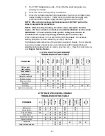
Page 48: ...replace major items or any items that call for special timing of adjustment procedures such as valves governor etc Have this work done by your Engine Service Dealer 31 HP DAIHATSU GAS ENGINE TROUBLESHOOTING TABLE PROBLEM NO FUEL IMPROPER FUEL DIRT IN FUEL LINE DIRTY AIR FILTER FAULTY SPARK PLUG ENGINE OVERLOADED BLOCKED FUEL FILTER INCORRECT OIL LEVEL INSUFFICIENT BATTERY CHARGE FAN PUMP BELT MISS...

Page 49: ...witch is turned to the ON position the buzzer emits intermittent beeps The intermittent beeps remind the user that the switch is ON and the hourmeter is running A switch left ON could also drain the battery b When the engine is running and the buzzer emits a continuous beep the buzzer is warning the user that the engine is overheating Perform the following steps 1 Disengage the mower blades and id...

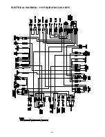
Page 50: ... 45 8 ELECTRICAL DIAGRAM 27 HP DAIHATSU DIESEL UNITS ...

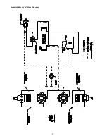
Page 51: ... 46 ELECTRICAL DIAGRAM 31 HP DAIHATSU GAS UNITS ...

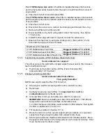
Page 52: ... 47 9 HYDRAULIC DIAGRAM ...

Page 53: ... expense of delivering the mower to the dealer for warranty work nor the expense of returning it back to the owner after repair or replacement Our responsibility in respect to claims is limited to making the required repairs or replacements and no claim of breach of warranty shall be cause for cancellation or rescission of the contract of sale of any Exmark mower Proof of purchase may be required ...

Page 54: ...charges or travel charges vi loss or damage to person or property other than that covered by the terms of this warranty vii any claims for lost revenue lost profit or additional cost as a result of a claim of breach of warranty or viii attorney s fees There are no representations or warranties which have been authorized and provided to the buyer of the turf equipment other than as set forth in thi...

Page 55: ... 50 ...
Page 56: ...roduct contains chemicals known to the State of California to cause cancer birth defects or other reproductive harm WARNING CALIFORNIA Proposition 65 Diesel engine exhaust and some of its constituents are known to the State of California to cause cancer birth defects and other reproductive harm MFG CO INC 2001 PART NO 103 1777 EXMARK MFG CO INC 402 223 6300 INDUSTRIAL PARK BOX 808 FAX 402 223 5489...

Reviews: