- 25 -
a)
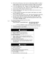
Check the voltage of the battery with a digital voltmeter. Locate the voltage
reading of the battery in the table below and charge the battery for the
recommended time interval to bring the charge up to a full charge of 12.6
volts or greater.
IMPORTANT:
When charging the battery, make sure the negative battery
cables are disconnected and the battery charger has an output of 16 volts
and 7 amps or less to avoid damaging the battery (see chart below for
recommended charger settings).
Voltage
Reading
Percent
Charge
Maximum
Charger Settings
Charging Interval
12.6 or greater
100%
16 volts/7 amps
No Charging Required
12.4 – 12.6
75 – 100%
16 volts/7 amps
30 Minutes
12.2 – 12.4
50 – 75%
16 volts/7 amps
1 Hour
12.0 – 12.2
25 – 50%
14.4 volts/4 amps
2 Hours
11.7 – 12.0
0 – 25%
14.4 volts/4 amps
3 Hours
11.7 or less
0%
14.4 volts/2 amps
6 Hours or More
5.1.4
Clean engine cooling system:
Service Interval: Daily or more often in dry conditions
a)
Wipe debris from screen in engine cover. Rotate engine cover forward and
wipe debris from radiator core as required. Inspect seals in engine cover
and replace as necessary.
5.1.5
Clean grass build-up under deck.
Service Interval: Daily
a)
Stop engine, wait for all moving parts to stop, and remove key.
b)
Raise deck to the transport (5” cutting height) position. Lift the front of unit
and support unit using jack stands or equivalent support.
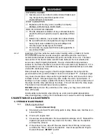
CAUTION
POTENTIAL HAZARD
♦
Raising the mower deck for service or maintenance
relying solely on mechanical or hydraulic jacks could
be dangerous.
WHAT CAN HAPPEN
♦
The mechanical or hydraulic jacks may not be enough
support or may misfunction allowing the unit to fall,
which could cause injury.
HOW TO AVOID THE HAZARD
♦
DO NOT rely solely on mechanical or hydraulic jacks
for support. Use adequate jack stands or equivalent
support.
c)
Clean out any grass build-up from underside of deck and in discharge chute.
5.1.6
Check mower blades.
Service Interval: Daily
a)
Stop engine, wait for all moving parts to stop, and remove key.
b)
Lift deck and secure in raised position as stated in Section 5.1.5.
c)
Inspect blades and sharpen or replace as required.
Summary of Contents for Laser Z XP
Page 50: ... 45 8 ELECTRICAL DIAGRAM 27 HP DAIHATSU DIESEL UNITS ...
Page 51: ... 46 ELECTRICAL DIAGRAM 31 HP DAIHATSU GAS UNITS ...
Page 52: ... 47 9 HYDRAULIC DIAGRAM ...
Page 55: ... 50 ...


