Exmark 000 & Higher Serial Nos. Operator'S Manual Download Page 34

Maintenance

Figure 16

Right-Hand Side of Unit Shown

1.

Re-install spring in outer
holes to reduce spring
tension.

3.

Remove e-ring and
washer.

2.

Weight transfer spring.

7. Re-install the left fender

8. For additional weight transfer adjustment, repeat

steps 4 through 7 on the right side of the unit.

Caster Pivot Bearings
Pre-Load Adjustment

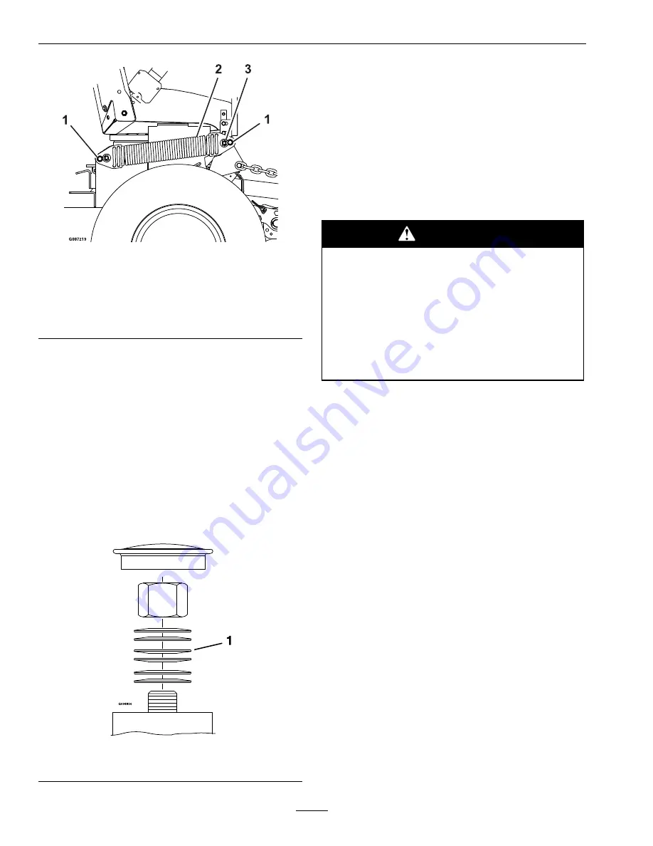
Remove dust cap from caster and tighten nyloc nut
until washers are flat and back off 1/4 of a turn
to properly set the pre-load on the bearings. If
disassembled, make sure the spring disc washers are
reinstalled as shown in Figure 17.

Figure 17

1.

Spring disc washers

Cleaning

Clean Engine Cooling
System

Service Interval: Before each use or daily

(May be required more
often in dry or dirty
conditions.)

CAUTION

Excessive debris around the engine cooling
air intake and inside of the pump drive
belt compartment and damaged or missing
rubber baffles can cause the engine and
hydraulic system to overheat which can
create a fire hazard.

Clean all debris from inside of pump drive
belt compartment daily.

1. Stop engine, wait for all moving parts to stop, and

remove key. Engage parking brake.

2. Clean all debris from rotating engine air intake

screen and from around engine shrouding.

3. Clean all debris from around the engine and drive

belts.

Remove Accumulated Debris
from Engine (Briggs &
Stratton Units Only)

Service Interval: Before each use or daily

Engine parts should be kept clean to reduce the risk
of overheating and ignition of accumulated debris.

1. Stop engine, wait for all moving parts to stop, and

remove key. Engage parking brake.

2. Remove front panel from engine and clean around

the intake manifold, fuel pump, and carburetor.

3. Reinstall the front panel.

Important:

Do Not use water to clean engine.

Use low pressure compressed air. See Engine
Owner’s Manual.

34

Summary of Contents for 000 & Higher Serial Nos.

Page 1: ...FRONTRUNNERTM AIR COOLED MODELS For Serial Nos 720 000 Higher Part No 4500 218 Rev A...

Page 2: ...d for information regarding The U S Environmental Protection Agency EPA and the California Emission Control Regulation of emission systems maintenance and warranty Keep this engine Owner s Manual with...

Page 3: ...ributor All Exmark equipment dealers and distributors are kept informed of the latest methods of servicing and are equipped to provide prompt and efficient service in the field or at their service sta...

Page 4: ...ssures 27 Check Condition Of Belts 28 Lubricate Grease Fittings 28 Lubricate Rear Caster Wheel Hub s 28 Lubricate Brake Handle Pivot 29 Lubricate Brake Rod Bushings 29 Lubricate Motion Control Bronze...

Page 5: ...mechanic s can not read English it is the owner s responsibility to explain this material to them Become familiar with the safe operation of the equipment operator controls and safety signs All operat...

Page 6: ...uring fueling static electricity can be released causing a spark which can ignite gasoline vapors A fire or explosion from gasoline can burn you and others and cause property damage Always place gasol...

Page 7: ...is engaged before starting engine Use seat belts Never operate the mower with damaged guards shields or covers Always have safety shields guards switches and other devices in place and in proper work...

Page 8: ...imate slope angle of the area to be mowed Use a walk behind mower and or a hand trimmer near drop offs ditches steep banks or water Figure 3 Figure 3 1 Safe Zone Use the mower here on slopes less than...

Page 9: ...r remove spark plug wire before making any repairs Disconnect the negative terminal first and the positive last Reconnect positive first and negative last Use care when checking blades Wrap the blade...

Page 10: ...n installed make sure current safety signs are visible New safety signs may be obtained from your authorized Exmark equipment dealer or distributor or from Exmark Mfg Co Inc Safety signs may be affixe...

Page 11: ...Safety 103 7218 107 2102 107 2112 109 2355 109 2356 1 Fast 3 Neutral 2 Slow 4 Reverse 11...

Page 12: ...Safety 109 2357 1 Fast 4 Reverse 2 Slow 5 Park Brake Release 3 Neutral 6 Park Brake Engage 109 2358 109 2377 109 2396 109 3637 12...

Page 13: ...Safety 109 7413 1 Cylinder extend 4 Slow 2 Cylinder retract 5 Choke on 3 Fast 6 Choke off 109 7949 109 2360 13...

Page 14: ...ne It is not necessary for the operator to be in the seat to start the engine Operator must be in seat when PTO is engaged brake is disengaged or motion control levers are moved in or engine will stop...

Page 15: ...qt 4 9 L 23HP Kohler Units 4 0 qt 3 8 L Hydraulic Filter Replaceable cartridge type P N 103 2146 25 microns No bypass Speeds 27HP Kohler 31HP Briggs Stratton Units 0 10 5 mph 16 9 km hr forward 0 6 6...

Page 16: ...83 cm 84 3 inches 214 cm Overall Length 23HP Kohler 27HP Kohler 31HP Briggs Stratton Without deck and floor pan folded 80 4 inches 204 2 cm 82 3 inches 209 0 cm 52 inch Deck 112 4 inches 285 5 cm 114...

Page 17: ...tor Mounting Bolts 72 77 ft lb 98 104 N m Wheel Hub Lock Nut 210 250 ft lb 285 339 N m Rollover Protection System Roll Bar Mounting Bolts 30 35 ft lb 41 47 N m Clutch Retaining Bolt secured with threa...

Page 18: ...Pull the lever up and rearward to engage the brake Push the lever forward and down to disengage the brake The unit must be tied down and brake engaged when transporting Ignition Switch Located on righ...

Page 19: ...rt Fill fuel tanks For best results use only clean fresh regular grade unleaded gasoline with an octane rating of 87 or higher Regular grade leaded gasoline may also be used however combustion chamber...

Page 20: ...the blades are engaged DANGER An uncovered discharge opening will allow objects to be thrown in an operator s or bystander s direction Also contact with the blade could occur Thrown objects or blade c...

Page 21: ...eutral Lock 4 Forward Driving Forward 1 Release the parking brake 2 Move the motion control levers inward to the center to the neutral unlocked position 3 To move forward in a straight line apply equa...

Page 22: ...unit on a ramp Use only a single full width ramp Do Not use individual ramps for each side of the unit If individual ramps must be used use enough ramps to create an unbroken ramp surface wider than...

Page 23: ...cation After the first 250 hours Change the hydraulic filter Before each use or daily Check the engine oil level Check the safety interlock system Check the rollover protections systems roll bar pins...

Page 24: ...ith the oil level below the LOW or ADD mark on the dipstick or over the FULL mark Check Battery Charge Service Interval Monthly WARNING CALIFORNIA Proposition 65 Warning Battery posts terminals and re...

Page 25: ...er must not crank 2 Check the kill circuits Run engine at one third throttle disengage parking brake and raise off of seat but do not get off of machine engine must initiate shutdown after approximate...

Page 26: ...on of the paper element Replace if dirty bent or damaged C Check the condition of the inner element Replace whenever it appears dirty typically every other time the paper element is replaced Clean the...

Page 27: ...ut 150 F 65 C fill to halfway between the HOT and COLD levels If the oil is at room temperature about 75 F 24 C fill only to the COLD level Check Auxiliary Hydraulic Oil Level Service Interval As requ...

Page 28: ...rly 4 Rear Caster Pivot 0 1 Yearly 5 Belt Idlers 1 2 Yearly 6 Motion Control Pivots 1 2 Yearly 7 Transfer Spring Ends 1 4 Yearly 8 Dual Tail Wheel Pivot if applicable 2 1 40 Hours See step 3 for speci...

Page 29: ...bearing adjustment often Spin the caster tire The tire should not spin freely more than 1 or 2 revolutions or have any side play If the wheel spins freely adjust torque on spacer nut until there is a...

Page 30: ...high enough to allow drive wheels to turn freely CAUTION Raising the mower for service or maintenance relying solely on mechanical or hydraulic jacks could be dangerous The mechanical or hydraulic ja...

Page 31: ...remove key before servicing cleaning or making any adjustments to the unit Pump Drive Belt Tension Self tensioning No adjustment necessary Pump Drive Belt Replacement 1 Stop engine wait for all moving...

Page 32: ...parts or hot surfaces may cause personal injury Keep fingers hands and clothing clear of rotating components and hot surfaces 1 This adjustment must be made with the drive wheels turning First raise...

Page 33: ...ition 2 Locate and loosen the knob under the rear of the left fender see Figure 15 Figure 15 1 Motion control lever 3 Fender knob 2 Left fender 3 Slide the fender forward and twist upward and outward...

Page 34: ...ke and inside of the pump drive belt compartment and damaged or missing rubber baffles can cause the engine and hydraulic system to overheat which can create a fire hazard Clean all debris from inside...

Page 35: ...il at a certified recycling center or according to your state and local regulations Battery Disposal DANGER Battery electrolyte contains sulfuric acid which is poisonous and can cause severe burns Swa...

Page 36: ...s closed 2 Open the fuel shutoff valve 3 Oil level in the crankcase is low 3 Add oil to the crankcase 4 The throttle and choke are not in the correct position 4 Be sure the throttle control is midway...

Page 37: ...indicator and motion control linkage need adjustment 3 Adjust the reverse indicator and the motion control linkage 1 Bypass valve is not closed tight 1 Tighten the bypass valve 2 Drive or pump belt is...

Page 38: ...DK GREEN ENGINE FUSE 15 AMP HEADLIGHT HARNESS YELLOW BLACK YELLOW BLACK DK BLUE WHITE ORANGE DK GREEN WHITE YELLOW BLACK YELLOW BLACK BLACK BLACK BLACK PINK BLACK LT BLUE DK GREEN DK GREEN ORANGE BLA...

Page 39: ...N WHITE LT GREEN LT GREEN LT BLUE GREY BROWN TAN LT BLUE LT BLUE VIOLET ORANGE ORANGE ORANGE DK BLUE WHITE DK GREEN TAN LT BLUE ORANGE GREY GREY BROWN BROWN BLACK BROWN RED TAN YELLOW ORANGE BLACK DK...

Page 40: ...Schematics Hydraulic Diagram CASE DRAIN CHARGE PUMP HIGH PRESSURE G007220 BYPASS VALVE BYPASS VALVE HIGH PRESSURE REVERSE HIGH PRESSURE FORWARD HIGH PRESSURE REVERSE HIGH PRESSURE FORWARD 40...

Page 41: ...ice Dealer before obtaining any warranty service Contact any Exmark Service Dealer to arrange service at their dealership To locate a dealer convenient to you access our website at www exmark com U S...

Page 42: ...Service Record Date Description of Work Done Service Done By 42...

Page 43: ...43...

Page 44: ...ONT RIDING ACCESSORIES CUSTOM RIDE SEAT SUSPENSION SYSTEM DUAL TAIL WHEEL FLOOR PAN EXTENDER HITCH KIT LIGHT KIT MICRO MULCH SYSTEM ROLL OVER PROTECTION SYSTEM ROPS ROTARY BROOM SNOW BLADE SNOWBLOWER...

Reviews: