2
|
GETTING STARTED WITH YOUR FIBER GUARDIAN
The installation process can be divided into the following main steps:
› Preparing for installation
› Installing the unit in a rack
› Connecting the power and the network cables
› Cleaning and connecting optical fi bers
› Turning on the unit
› Setting up the unit (platform application)
› Setting up the unit (optical application)
PREPARING FOR INSTALLATION
Before installing your unit, you should take the following into consideration:
› The chosen location provides adequate clearance for maintenance procedures, including a front opening of the drawer that
allows access to the OTDR module inside the unit and enough slacks for jumpers if you want to open the drawer without
disconnecting all ports.
› The location is an environmentally-controlled area that meets the minimum operating parameters.
› The location is isolated from strong electromagnetic fi elds produced by electrical devices.
› The power cable and power supply are compatible with your power service.
› The power source is properly grounded and falls within the internal power supply rating.
› The location is in an Electrostatic discharge (ESD)-safe work area.
INSTALLING YOUR UNIT IN A RACK
› The rack (which is not included with the unit) should provide suffi cient vertical clearance to insert the unit. The height of the
unit is two rack units (2U) high or about 3 ½ in.
› All electrical cabling can be connected only through the back panel.
To install the mounting brackets on your unit:
1. Position the unit so that its bottom panel rests on a fl at surface, such as a table.
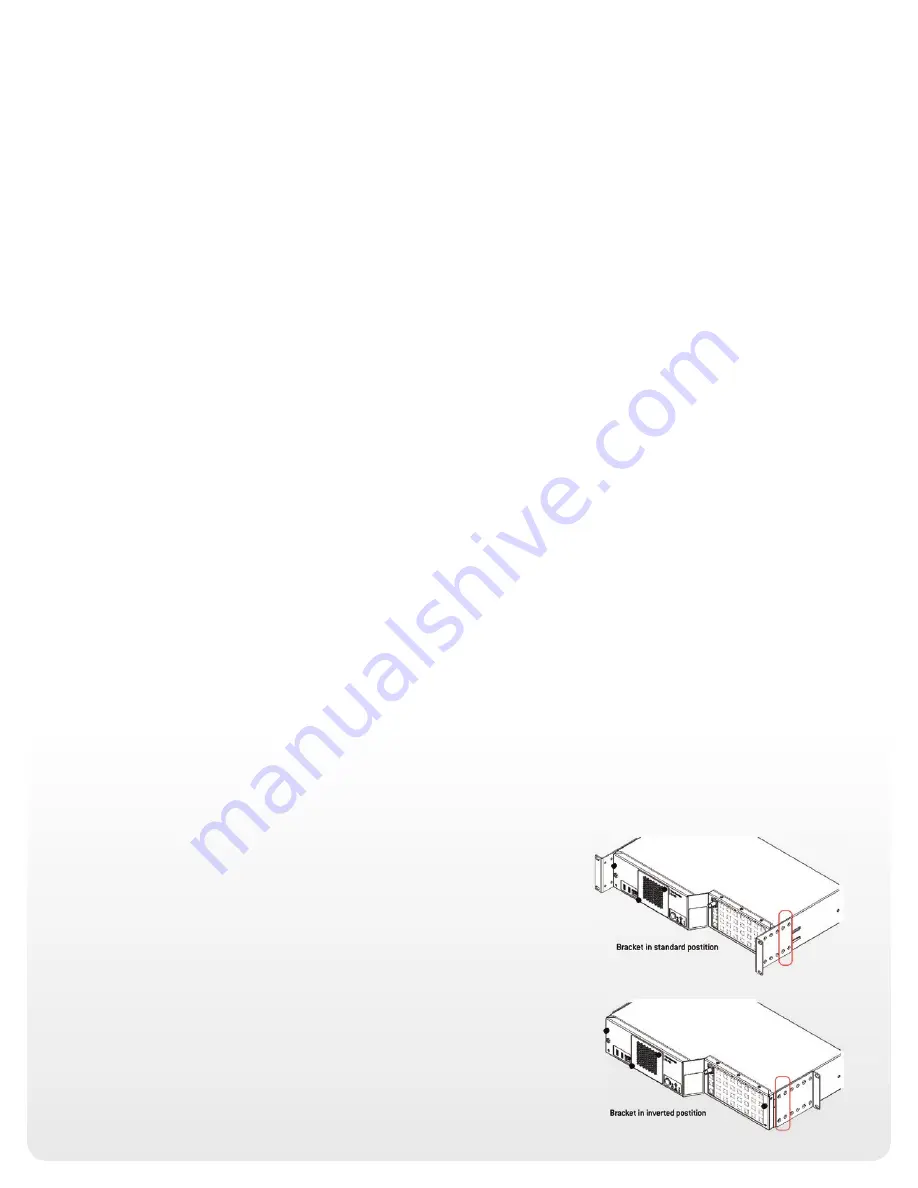
2. Align the holes of the fi rst bracket with the holes of the unit casing at the
position that best suits your installation needs. You can even invert position of
the mounting bracket, if necessary.
3. Fix the fi rst bracket on the unit with the supplied screws (four screws per
bracket).
4. Repeat steps 3 and 4 with the other bracket, ensuring that you place the bracket
at the exact same position (the orientation of the bracket, as well as the set of
holes on the bracket and on the unit’s casing).
5. Place the unit in the rack at the desired height.
6. Fix the unit in place using four 10-32 x 1/2 in. screws (four M6 screws for the
ETSI racks).
Summary of Contents for Fiber Guardian FG-750
Page 1: ...GETTING STARTED WITH YOUR FIBER GUARDIAN...
Page 15: ...15 NOTES...


