Excelsior DK4EXA075 Installation, Operation And Maintanance Download Page 39

39

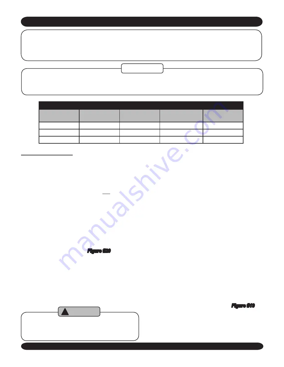
TABLe 8: ReCoMMended MiniMuM CHiMney siZes

FiRinG RATe

(gph)

CHiMney

HeiGHT 

(ft)

noMinAL

CHiMney

rOunD 

LinEr inSiDE

sQuARe 

LinEr inSiDE

0.60 -1.30

15

8” x 8”

6”

6 ¾” x 6 ¾”

1.31 -1.80

15

8” x 8”

7”

6 ¾” x 6 ¾”

1.81 -2.00

20

8” x 8”

8”

6 ¾” x 6 ¾”

For elevations above 2,000 feet above sea level, add 3 feet to the chimney heights.

CHIMNEY AND CHIMNEY CONNECTIONS

For oil fired boilers with connections to vents or chimneys, vent installations shall be in accordance 

with applicable provisions of nFPA31 insTALLATion oF oiL BuRninG eQuiPMenT,  latest revision, 

(u.s.) or CsA B139 (Canada) and applicable provisions of local building codes.

Fresh air (ventilation) is important to proper venting. Ventilation and venting are two parts of the same sys-

tem. Inadequate ventilation will result in inadequate venting. Always be sure to have enough ventilation to 

ensure proper venting.

NOTICE

CHiMney VenTinG

Chimney venting is an important part of a safe and 

1. 

efficient oil fired appliance system. Requirements of 

NFPA31 – Standard for the Installation of Oil-Burning 
Equipment and NFPA 211 – Standard for Chimneys, 
Fireplaces, Vents, and Solid Fuel-Burning Appliances 
for installations in the United States and the require-
ments of CSA B139 – Installation Code for Oil-burn-
ing Equipment. (Installations in Canada) must be met.

Ensure that there is sufficient draft during the entire 

2. 

heating season to allow for the safe evacuation of flue 

gasses. 

The boiler can be vented into a fireclay

3. 

 tile-lined 

masonry chimney constructed from type L vent or a 
factory built chimney that complies with the type HT 
requirements of UL103. See 

Figure #20

 for recom-

mended installation.

Chimney Inspection – Prior to the installation of any 

4. 

new or replacement fuel burning equipment the 

chimney shall be inspected by a qualified installer. 

The chimney shall be examined  by a qualified person 

in accordance with the requirements of NFPA 211, 
Standard for Chimneys, Fireplaces, Vents, and Solid 
Fuel Burning Appliances or CSA B139.

de-rating the appliance may cause conden

-

sation on the interior walls of the chimney 

and the boiler.

WARNING

!


Loose Mortar – Loose mortar could be an indica-

A. 

tion of prior history of condensing flue gases upon 

the inside walls of the chimney. Colder climates are 
more susceptible to this condition. Under no circum-
stances shall a  chimney of this condition be used 
until it meets the requirements of NFPA 211 or CSA 
B139.

Unlined Chimney – Under no circumstances shall 

B. 

a chimney constructed of brick only be used.  Only 
approved clay liners or listed chimney lining systems 

shall be used as specified in NFPA 31 or CSA B139

Abandoned Openings – Openings through the chim-

C. 

ney wall that are no longer used shall be sealed in 
accordance to NFPA 211.  Often abandoned open-
ings are improperly sealed and usually covered by a 
gypsum wall covering.

Clean Chimney – Chimney shall be free of all loose 

D. 

debris.

Install draft regulator at least 18” above breach. At 

5. 

least 18” of straight run up stream of regulator will 
ensure proper operation.

Draft Regulator – the draft regulator supplied with the 

6. 

boiler must be used with this appliance.  No other 
draft regulator shall be used.  Refer to 

Figure #19

.

Summary of Contents for DK4EXA075

Page 1: ...n ISO 9001 2000 Certified Company EXCELSIOR High Efficiency Oil Fired Hot Water Boiler MEMBER The Hydronics Institute Dunkirk BOILERS 85 Middle Road Dunkirk NY 14048 www dunkirk com Installation opera...

Page 2: ...A165 The boiler is a natural draft oil fired hot water boiler comprised of cast iron sections The boiler is avail able with 4 5 6 or 7 cast iron sections These sections are held together by push nippl...

Page 3: ...s breech gasket flue cover gasket etc or attempt any service or repair work involving RCF or fiberglass without wearing the following protective gear A national Institute for Occupational Safety and H...

Page 4: ...OILER 9 ASSEMBLING THE BOILER 13 BOILER SYSTEM PIPING 21 PIPING DIAGRAMS 23 FUEL OIL PIPING 35 ELECTRICAL CONNECTIONS 37 CHIMNEY AND CHIMNEY CONNECTIONS 39 OPERATING THE BOILER SYSTEM START UP 43 OIL...

Page 5: ...actices All wiring on boilers installed in Canada shall be 2 made in accordance with the Canadian Electrical Code C22 2 and or local regulations The following terms are used throughout this manual to...

Page 6: ...on on combustible flooring Do not install boiler on carpeting Do not tamper with or alter the boiler or controls Inspect flue ways at least once a year Preferably at the start of the heating season Th...

Page 7: ...the expansion tank s air charge will need to be increased to match the fill pressure Consult the expansion tank manufacturer s guidelines for sizing and selection Purging the heating system of air and...

Page 8: ...the system piping The Net I B R Ratings shown are based on a piping and pickup factor of 15 in accordance with the I B R Standard as published by the Hydronics Institute The Net I B R Rating of the b...

Page 9: ...8 17 3 4 7 34 1 4 27 1 2 17 3 4 LOCATING THE BOILER TABLE 2B BOILER CLEARANCES Unit Combustible Clearance Accessibility Clean ing and Servicing Top 12 24 Right Side 2 24 Left Side 2 24 Floor Combusti...

Page 10: ...10 NOTE ALWAYS KEEP THE MANUAL FUEL SUPPLY VALVE SHUT OFF IF THE BURNER IS SHUT DOWN FOR AN EXTENDED PERIOD OF TIME INSTALLATION REQUIREMENTS Figure 2 General Requirements for a typical installation...

Page 11: ...uct cross sectional area shall be same as opening free area FRESH AIR FOR COMBUSTION Horizontal Ducts c Minimum free area of 1 square inch per 2 000 BTU per hour input of all equipment in space Duct c...

Page 12: ...DUCT CAPACITIES Through Louvers Fresh Air Duct Size Mesh Screen Wood Louvers Metal Louvers Btuh Btuh Btuh 3 x 12 144 000 36 000 108 000 8 x 8 256 000 64 000 192 000 8 x 12 384 000 96 000 288 000 8 x 1...

Page 13: ...nto slotted mounting bracket holes NOTICE Inspect Swing door insulation and rope gasket 5 Inspect fiber rope located on the swing door The A rope must be evenly distributed around the perimeter of the...

Page 14: ...ion well 14 Install in upper NPT port facing front See Figure 6 Install Aquastat Control Harness Assembly 15 Loosen mounting screw on bottom of case Insert sensor into immersion well Mount control on...

Page 15: ...ional ASSEMBLING THE BOILER No valves may be installed between boiler and controls manifold or safety relief valve WARNING TABLE 4 CONTROLS MANIFOLD PORT SCHEDULE PORT PORT SIZE DESCRIPTION A 1 4 NPT...

Page 16: ...evel Manual Reset optional and the harness from the Aquastat through the rear jacket panel See Figure 11 Connect the molex plugs on the end of each wire harness to its respective plug on the control p...

Page 17: ...E TO WHITE BLACK TO YELLOW GREEN TO GROUND SCREW Figure 10 Circulator wiring Figure 11 SUPPLIED JUMPERS AQUASTAT CONTROL HARNESS 120 VAC POWER BURNER HARNESS Ensure all conduit is secured to prevent c...

Page 18: ...ng a diagonal sequence E Plug burner power cord into power harness F Attach flexible oil hose included in parts box G Install the Drain Valve 20 Install drain valve with hose connection facing right o...

Page 19: ...in the tank This compressed air cushion permits the water in the system to expand as the temperature changes and assures a full measure of water even in the highest radiation unit of the system The di...

Page 20: ...provide the circulation required by the heating system The circulator should be connected to the supply main and must be wired into the boiler s electrical system See the System Piping section for pi...

Page 21: ...ust be mounted 3 in the 3 4 supply manifold tapping or in the system piping above the boiler The minimum safe water level of a hot water boiler is just above the highest water containing cavity of the...

Page 22: ...ter zone A inch bypass line must be installed as shown in the piping diagrams for the systems identified above BOILER SYSTEM PIPING A bypass valve cannot protect the boiler from sus tained condensing...

Page 23: ...R DRAIN VALVE CONTROLS MANIFOLD TO SYSTEM FROM SYSTEM CIRCULATOR PRESSURE REDUCER VALVE CHECK VALVE AIR SEPARATOR HOSE BIB EXPANSION TANK Diagram 1 Standard piping near boiler No valve may be installe...

Page 24: ...Y ZONE CIRCULATOR EXPANSION TANK FLOW CONTROL VAVLE SHUT OFF VALVE PRESSURE REDUCER VALVE CHECK VALVE BALL VALVE AIR SEPARATOR ZONE VALVE HOSE BIB PIPING DIAGRAMS 24 Diagram 2 Single Zone system with...

Page 25: ...CE CONSIDER USING ZONE CIRCULATOR SEE FIGURE 5 ZONE 4 CIRCULATOR SHUT OFF VALVE PRESSURE REDUCER VALVE CHECK VALVE EXPANSION TANK AIR SEPARATOR ZONE VALVE HOSE BIB FLOW CONTROL VALVE PIPING DIAGRAMS 2...

Page 26: ...CIRCULATOR CH CIRCULATOR CIRCULATOR FLOW CONTROL VALVE SHUT OFF VALVE PRESSURE REDUCER VALVE CHECK VALVE BALL VALVE AIR SEPARATOR ZONE VALVE HOSE BIB EXPANSION TANK PIPING DIAGRAMS 26 Diagram 4 Multi...

Page 27: ...DHW CIRCULATOR CIRCULATOR SHUT OFF VALVE PRESSURE REDUCER VALVE CHECK VALVE BALL VALVE AIR SEPARATOR ZONE VALVE HOSE BIB FLOW CONTROL VALVE EXPANSION TANK PIPING DIAGRAMS 27 Diagram 5 Multizone system...

Page 28: ...PREVENT FORCED FLOW IN SECONDARY ZONE 4 DHW CIRCULATOR CIRCULATOR SHUT OFF VALVE PRESSURE REDUCER VALVE CHECK VALVE BALL VALVE AIR SEPARATOR ZONE VALVE HOSE BIB FLOW CONTROL VALVE EXPANSION TANK PIPIN...

Page 29: ...VALVE FOR OPTIMUM TANK PERFORMANCE CONSIDER USING ZONE CIRCULATOR SEE FIGURE 13 CIRCULATOR SHUT OFF VALVE PRESSURE REDUCER VALVE CHECK VALVE BALL VALVE AIR SEPARATOR ZONE VALVE HOSE BIB FLOW CONTROL V...

Page 30: ...OR LOCATION ZONE 4 USE FULL PORT ZONE VALVE DHW CIRCULATOR CIRCULATOR SHUT OFF VALVE PRESSURE REDUCER VALVE CHECK VALVE BALL VALVE AIR SEPARATOR ZONE VALVE HOSE BIB FLOW CONTROL VALVE EXPANSION TANK P...

Page 31: ...RNATE CIRCULATOR LOCATION TO SYSTEM FROM SYSTEM CIRCULATOR SHUT OFF VALVE PRESSURE REDUCER VALVE CHECK VALVE BALL VALVE 3 WAY MIXING VALVE AIR SEPARATOR HOSE BIB EXPANSION TANK 31 Diagram 9 Bypass pip...

Page 32: ...ROM SYSTEM V2 V1 CIRCULATOR SHUT OFF VALVE PRESSURE REDUCER VALVE CHECK VALVE BALL VALVE AIR SEPARATOR ZONE VALVE EXPANSION TANK 32 Bypass piping fixed low temp only Diagram 10 Adjust the two throttli...

Page 33: ...ON TO SYSTEM FROM SYSTEM CIRCULATOR SHUT OFF VALVE PRESSURE REDUCER VALVE CHECK VALVE BALL VALVE AIR SEPARATOR HOSE BIB FLOW CONTROL VALVE 4 WAY MIXING VALVE EXPANSION TANK 33 Diagram 11 Bypass piping...

Page 34: ...Piping for Combination Heating and Cooling Refrigeration System WATER CHILLER AIR CUSHION TANK CIRCULATOR SHUT OFF VALVES SUPPLY MAIN TO COMBINED HEATING COOLING SYSTEM RETURN MAIN FROM COMBINED HEAT...

Page 35: ...ances can copper with sweat style connectors be used WARNING Some jurisdictions require the use of a fusible shutoff valve at the tank and or the burner In addition some jurisdictions require the use...

Page 36: ...mber of Boiler Section Total Volume Gallons 4 3 6 5 4 3 6 5 1 7 5 9 TABLE 7 PIPING WATER VOLUMES PIPE SIZE COPPER PIPE FACTOR STEEL PIPE FACTOR 82 5 63 5 40 0 36 0 1 23 3 22 2 1 15 3 12 8 1 10 8 9 5 2...

Page 37: ...electrical work Each boiler must be protected with a properly sized fused disconnect Never jump out or make inoperative any safety or operating controls Positively assure all electrical connections ar...

Page 38: ...38 ELECTRICAL CONNECTIONS 240007363 Figure 18 Wiring Diagram All Models optional equipment shown...

Page 39: ...d from type L vent or a factory built chimney that complies with the type HT requirements of UL103 See Figure 20 for recom mended installation Chimney Inspection Prior to the installation of any 4 new...

Page 40: ...chimney may be a sign of condensate dam age to the chimney A chimney professional shall be contacted immediately to examine the damage and recommend a solution Long term operation while in this condi...

Page 41: ...41 Chimney and chimney connections Figure 20 Typical Chimney Locations Figure 19 Proper draft vent locations...

Page 42: ...mney connector or stack NFPA 31 and CSA B139 have information to help the 2 installer make an appropriate choice of venting mate rials In some cases a chimney may have to be lined to create sufficient...

Page 43: ...mpletion open all zone valves Close purge valve continue filling the system until H the pressure gauge reads 12 psi Close shut off valve in cold water supply piping The maximum operating pressure of t...

Page 44: ...ess any key Control Operating Characteristics The L7248A can be in any three 3 operational states Normal High Limit and Error The controller moves back and forth from High Limit to Normal state as par...

Page 45: ...e port Locate oil pressure adjusting screw and turn screw II to obtain proper pump pressure refer to Burner Settings section of this manual To check the cut off pressure deadhead a reliable III pressu...

Page 46: ...his feature limits the number of recycle trials for each call for heat to a maximum of three trials If the flame is lost three times and does not successfully satisfy a call for heat the R7184 locks o...

Page 47: ...witch timing indicated on label and control enters Restricted Mode Indicator light flashes 1 2 second on 1 2 Second off Ignition and motor stop and oil valves closes To reset from Restricted Mode Pres...

Page 48: ...e burner s air adjustment to obtain a smoke reading showing a trace smoke reading Once the smoke reading is a trace measure the CO2 and as an in surance margin increase the air to sufficiently reduce...

Page 49: ...49 This page intentionally left blank...

Page 50: ...AIR BAND AIR SHUTTER Z OR AIR HEAD SETTING BECKETT AFG 4 L2 3 375 U 2 675 0 75 140 0 65 X 60B 0 7 N A 5 L2 3 375 U 2 675 1 140 0 85 X 60B 2 10 N A 6 V1 2 75 M 2 675 1 30 140 1 10 X 60AS 1 10 0 7 V1 2...

Page 51: ...burner part numbers BURNER MAKE BOILER MODEL BURNER PART PUMP PRESSURE DELAVAN HAGO DANFOSS Beckett AFG 75 240007232 140 PSIG 0 65 X 60 B 0 65 X 60 B N A 100 240007233 140 PSIG 0 85 X 60 B 0 85 X 60 B...

Page 52: ...to the valve manufacturer s instructions packaged with the valve for more details CONVENTIONAL EXPANSION TANK As noted in the EQUIPMENT AND ACCESSORIES section DIAPHRAGM EXPANSION TANK As noted in th...

Page 53: ...system other than the expansion tank must be full of water for satisfactory operation Water should be added to the system until the boiler pressure gauge registers 12 psi To insure that the system is...

Page 54: ...a manner that will not strip the threads when service is completed WARNING If Boiler is not used during winter time it must be fully drained to prevent freeze damage C FREQUENT WATER ADDITION Althoug...

Page 55: ...2nd pass G Vacuum the loose debris in the bottom of the com H bustion chamber and smoke box Clean the combustion chamber and baffles 2 Use a wire or fiber bristle brush to clean the surfaces of the c...

Page 56: ...pe recommended for use on this boiler See label on side of boiler These are general instructions for cleaning an oil burner For specifics consult the burner manufacturer s instructions OIL BURNER CLEA...

Page 57: ...chills the flame and causes smoke and unburned fuel to pass out of the combustion chamber and clog the flue ways of the boiler Cold Oil If the oil temperature approaching the fuel E pump is 40 F or c...

Page 58: ...switches installed Look for a red plate which may be on the service switch Controls out of adjustment Reset according to instructions Circulating pump not running Check over current protection Check r...

Page 59: ...____________________________________________ _________________________________________________________ _________________________________________________________ _______________________________________...

Page 60: ...te Service Performed Company Name Tech Initials Company Address Phone For technical assistance with this product call toll free 1 800 325 5479 ECR International PO Box 4729 Utica NY 13504 4729 www ecr...

Reviews: