8
14 Pin Secondary Wire Harness (cont’d)
MANUAL TRANSMISSION CONNECTION:
The Gray wire also serves as a door
pin input (must see all doors) which is required to perform the “manual transmission
setup procedure” (detailed in the operation guide)� Diode isolate the hood input from
the door input using two 1 or 2 amp diodes facing the cathodes (stripes) towards the
vehicle wires� If the vehicle’s door pin wire is positive, you must invert the signal with
a relay�
YELLOW - ALARM IGNITION CONTROL (+) OUTPUT
This output controls the ignition input to an outboard aftermarket alarm or keyless
entry� When remote start is activated, this wire prevents the keyless/alarm from
receiving an ignition ON input to allow for keyless entry operation� Otherwise, it’s a
direct pass through of the ignition circuit�
CONNECTION:
Connect this wire directly to the outboard keyless entry/alarm’s
ignition input wire�
WHITE/BLUE WIRE - REMOTE START ACTIVATION (-) INPUT
This input will activate the system’s remote start function when it receives a nega-
tive pulse� Another pulse during remote start operation will turn off the remote start�
CONNECTION:
Connect this wire to any device that you desire to activate the
remote start feature. It requires a negative pulse input.
LT� GREEN/RED WIRE - OEM ALARM ARM (-) OUTPUT
This output provides a 250mA negative pulse when remote start is turned off and
when the system’s alarm is armed�
CONNECTION:
Connect this wire to the vehicle’s OEM alarm arm circuit� Typically,
it will show ground when the door cylinder key is turned to the lock position�
RED/WHITE WIRE - TRUNK RELEASE / CH2 (-) OUTPUT
This output provides a 250mA negative output when the trunk release/CH2 func-
tion is activated by the controller� The output will remain as long as the controller
button(s) is held�
CONNECTION:
Connect this wire to the vehicle’s existing trunk release switch if it
is a low current negative circuit� If the circuit is a high current ground or a positive
circuit, the use of a relay is required.
This output provides a 250mA negative pulse when remote start is activated and
when the system’s alarm is disarmed�
CONNECTION:
Connect this wire to the vehicle’s OEM alarm disarm circuit� Typi-
cally, it will show ground when the door cylinder key is turned to the unlock position�
LT� GREEN/BLACK WIRE - OEM ALARM DISARM (-) OUTPUT
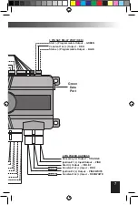
These ports provide a direct digital interface for any Omega IntelliKit or Ome-
gaLink interface modules and upgrades like the CarLink smartphone interface�
They eliminate the need for several wire-to-wire connections� The ports support the
standard D2D (Trilogix) protocol and the ADS (iDataLink) protocol� The black port
allows direct flashing of the firmware and feature programming via our
OmegaLink Weblink plug-in at www�omegaweblink�com�
Green & Black Data Port


