background image

37

OPTIC EXCALIBUR

English

T

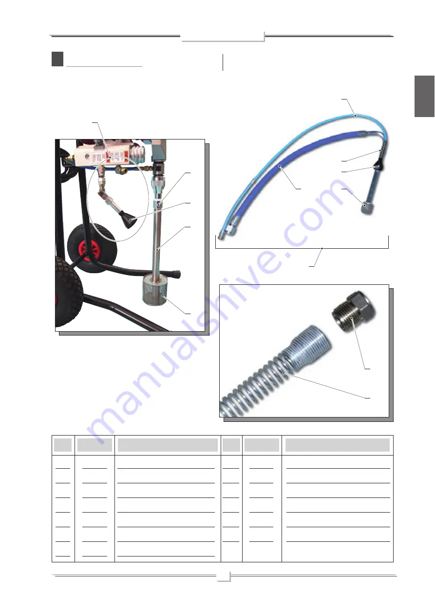
ACCESSORIES

WARNING

: Always indicate code and quantity for each part required.

Pos.

Pos.

Complete jointed fi tting

Dispersion bell

Filter

Union

Dip hose

Assembly

Recirculation pipe

Spring

Dispersion bell

Filter

Flexible hose

Nut

Spring

37600

18350

37216

16602

16601

18370

18367

18095

18350

16802

18375

18609

18608

1

2

3

4

5

6

7

8

9

10

11

12

13

Code

Description

Code

Description

7

1

4

2

5

3

8

9

10

11

6

12

13

Summary of Contents for Larius

Page 1: ...OPERATING AND MAINTENANCE INSTRUCTION ENGLISH OPERATING AND MAINTENANCE INSTRUCTION with optic sensor with optic sensor PAINTING EQUIPMENT ...

Page 2: ......

Page 3: ...ECIFICALLY MENTIONED INTHIS MANUAL Thank you for choosing a LARIUS S R L product As well as the product purchased you will receive a range of support services enabling you to achieve the results desired quickly and professionally CORRECT PROCEDURE OF DECOMPRESSION p 15 REPLACING THE GASKET KIT AND SETTING THE HYDRAULIC PRESSURE SWITCH p 16 Refitting and setting procedure p 17 REPLACEMENT OF THE PU...

Page 4: ...t indicates wound and finger squashing risk due to movable parts in the equipment Tenersi lontano dalle parti in movimento Do not use the equipment without the proper protection Before any inspection or maintenance of the equipment carry out the decompression procedure explained in this manual and prevent any risk of the equipment starting unexpectedly Report any risk of chemical reaction or explo...

Page 5: ...uum The product is sucked pushed towards the pump outlet and then sent to the gun through the flexible hose A mechanical device on the side of the reduction gear casing allows to adjust and control the pressure of the material coming out of the pump When the pump reaches the set value the motor stops and starts again when the value decreases Asafetyvalveavoidingoverpressure guaranteesthetotalrelia...

Page 6: ...ase RUN GENERATOR SUPPLY MOTOR POWER MAX WORKING PRESSURE MAX DELIVERY MATERIAL OUTLET WEIGHT LEVEL OF THE SOUND PRESSURE LENGTH WIDTH HEIGHT 230Vac 50Hz minimum 4Kw asynchronous 0 75 kW 210 bar 2 1 L min M16 x 1 5 M 17 Kg 80dB A A 450 mm B 460 mm C 550 mm TECHNICAL DATA EXCALIBUR 230Vac 50Hz minimum 4Kw asynchronous 0 75 kW 210 bar 2 1 L min M16 x 1 5 M 18 Kg 80dB A A 580 mm B 540 mm C 995 mm C A...

Page 7: ...S 1 2 3 4 5 POS 6 7 8 9 ON OFF switch Pressure control knob Reduction box Pumping group High pressure flexible pipe of compensation Description Suction filter Safety recirculation valve Airless manual gun Trigger safety clamp Description 5 7 2 7 6 4 1 2 3 9 8 ...

Page 8: ... EMPLOYEES ABOUT ALLTHOSERISKSSTEMMINGFROMACCIDENTS ABOUT THEUSEOFSAFETYDEVICESFORTHEIROWNSAFETY AND ABOUT THE GENERAL RULES FOR ACCIDENT PREVENTION IN COMPLIANCE WITH INTERNATIONAL REGULATIONS ANDWITHTHE LAWS OFTHE COUNTRY WHERE THE PLANT IS USED Read carefully and entirely the following instruc tions before using the product Please save these instructions in a safe place The unauthorised tamperi...

Page 9: ... of corrosion and explosion TIGHTENANDCHECKALLTHEFITTINGSFORCONNEC TIONBETWEENPUMP FLEXIBLEHOSEANDSPRAYGUN BEFORE USING THE EQUIPMENT ALWAYS USE THE FLEXIBLE HOSE SUPPLIED WITH STANDARD KIT THE USE OF ANY ACCESSORIES OR TOOLING OTHER THAN THOSE RECOMMENDED IN THIS MANUAL MAY CAUSE DAMAGE OR INJURE THE OPERATOR THE FLUID CONTAINED IN THE FLEXIBLE HOSE CAN BE VERY DANGEROUS HANDLE THE FLEXIBLE HOSE ...

Page 10: ...upply cable is provided without plug Use a plug which guarantees the plant earthing Only a technician or a skilled person should perform the connection of the plug to the electric cable CHECK ON POWER SUPPLY Makesurethattheelectricalsystemisearthedand complies with regulations Voltage F2 F3 F1 ...

Page 11: ... 2 5 mm2 with a maximum lengthof50mt Higherlengths andlowerdiameters can provoke excessive voltage falls and also an anomalous working of the equipment Lift the suction pipe and dip it into the solvent tank Ensure the gun F3 is without nozzle Press the switch F4 of the equipment ON I Turn clockwise the pressure control knob F5 so as the machine works at idle speed WASHING OFTHE NEW EQUIPMENT The e...

Page 12: ...ay from the pump in order to avoid the contact between the solvent fumes and the electric motor Neveruseproductscontaininghalogenhydrocarbons asmethylene chloride Iftheseproductscomeintocontactwithaluminiumparts of the equipment can provoke dangerous chemical reactions with risk of explosion Make sure the product to be used is compatible with the materials employed for manufacturing the equipment ...

Page 13: ... pressure to the minimum turn counterclockwise the pressure control knob H1 Press the switch H2 placed on the box of the electric motor to stop the equipment Press the switch ON I of the equipment and turn a little the pressure control knob clockwise G3 so as the machine works at the idle speed SPRAY ADJUSTMENT Slowly turn clockwise the pressure control knob to reach the pressure value in order to...

Page 14: ...lve H3 toreleasethepressure in the circuit Lift the suction pipe and replace the product tank with that of the solvent ensure it is compatible with the product being used Unscrew the gun nozzle do not forget to clean it with sol vent Press the switch H2 ON and turn a little the pressure control knob H1 clockwise so as the machine works till the motor starts Make sure the solvent recycles the washi...

Page 15: ...ht in order to avoid wastes but not excessively to prevent the piston from seizing and the gaskets from wearing For tightening use the wrench supplied ref 11503 WARNING PLATE J Minimum power available 4 kW single phase asynchronous Usethelubricantsupplied ref 16325 toallowaneasysliding of the piston inside the gasket group Daily top up the packing nut ALWAYS DISCONNECT THE POWER SUPPLY AND RELEASE...

Page 16: ...delivery valve dirty Nozzle too big or worn The product is too dense The filter of the gun butt is too fine The nozzle is partially clogged The product is too dense The filter of the gun butt is too fine The nozzle is worn The gaskets of the pumping group are worn Suction or delivery valve dirty Recirculating safety valve defective Check the correct connection to the power supply Check the extensi...

Page 17: ...entherecirculating safetyvalve L4 toreleasetheresidual pressure always clockwise WARNING If the equipment is still under pressure after per forming the operations above described because ofthenozzleortheflexiblehoseclogged proceed as follows Loosen very slowly the gun nozzle Release the clamp Pointthegunintothecontaineroftheproduct and press the trigger to release pressure Loosen very slowly the f...

Page 18: ...ut M5 on the threaded section M6 Drain the liquid that is still pressurised into the product collec tion container M2 using the gun M3 until it is completely decompressed the reading on the pressure gauge must be 0 bar Release the pressure in the hydraulic circuit by turning the knob on the pressure switch M1 as far as possible turn anticlockwise Theringnut M5 willbeusedasapointofreference for sub...

Page 19: ...While the unit is still disassembled turn the setting knob M1 clockwise to tighten it until it is at the end of its thread Refit the unit M8 in its original position Check gaskets a b c and d and replace if necessary Grease the gaskets using Vaseline The ring nut M5 must be in the position marked before it was disassembled Open Close M4 M4 M5 M7 M8 d Ref 11955 b Ref 18554 a Ref 18755 M1 M5 c Ref 1...

Page 20: ... the pressure gauge YES If the reading on the pressure is not as indicated proceed as follows Value lower than 200 bar NO NO Loosen the ring nut M5 by 1 2 a turn and tighten the knob M1 all the way Checkthepressureagainasdescribedinthepreviouspoints and repeat the process until the correct pressure reading is obtained 200 210 bar Tighten the ring nut M5 well using a 30 mm spanner Value higher than...

Page 21: ...move it Remove the locking pin N5 using pliers N6 Unscrewthefixingringnut N7 totheendofthethreadusing a 45 mm spanner Unscrew the suction casing using a 32 mm spanner as illu strated If necessary remove the suction pipe N8 before continuing with the other operations Always disconnect the power supply and release pressurebeforegoingonwiththeoperations follow the correct procedure of decompression U...

Page 22: ...pplied Turn anticlockwise as shown Use a 36 mm spanner to unscrew the pump unit as shown Remove the pump unit N13 from the foot valve N14 as shown Inspect the two parts separately PIT STOP MAINTENANCE Replacement of upper and lower gaskets 25 minutes REPLACINGTHE FOOT VALVE SEALS ReplacetheTeflongasket N15 locatedundertheballseating N16 Check that the surfaces of the ball seating N16 and the ball ...

Page 23: ...N19 from the pump unit housing N18 as shown Unscrew the gasket compression ring nut N20 comple tely All the gaskets in the unit must be replaced at the same time to allow the machine to work properly Remove the upper stainless steel female ring N21 as shown N16 N15 N17 N18 N19 N20 N21 N21 ...

Page 24: ...he pump unit housing as shown Remove the lower stainless steel male ring N22 as shown Fit the new gasket kit according to the component sequence shown in the figure Upper white polyethylene 1 Red polyurethane 2 N22 Waxed leather 3 Red polyurethane 4 5 Lower white polyethylene ...

Page 25: ...m N19 in a vice as shown Upper white polyethylene Red polyurethane Waxed leather Stainless steel female ring Red polyurethane Lower white polyethylene Stainless steel male ring N23 N24 Upper white polyethylene Red polyurethane Waxed leather Red polyurethane Lower white polyethylene Stainless steel male ring Stainless steel female ring N19 ...

Page 26: ...movethestem N19 as indicated Remove the complete gasket kit N25 from the stem N19 as shown in order to replace it N19 N25 White polyethylene Scraper Ref 18648 White polyethylene White polyethylene N19 Red polyurethane Stainless steel female ring Red polyurethane Stainless steel male ring Red polyurethane Red polyurethane Stainless steel male ring Stainless steel female ring White polyethylene ...

Page 27: ...rease as shown Vaseline is recommended for this task Replace the red polyurethane lipped gasket N26 for the valve piston Refit according to the assembly order and the alignment of the lip as shown Check the surfaces of the ball N27 and ball seating N28 and replace both if damaged Assemble the components as shown Lubricate the gaskets N29 and the stem Vaseline is recommended for this task N19 N18 N...

Page 28: ...eviously complete a full stroke as shown Usethepin N12 suppliedtotightenthegasketcompression ring nut N11 Close this until it is fully touching without forcing CORRECT POSITIONING OFTHE PUMP UNIT Once the unit has been refitted proceed as follows Checkthepositionoftheconrod whichshouldbepositioned at its lower stopping point Put the entire pump unit N10 inside the reduction cover N33 as shown N32 ...

Page 29: ...4 Check that the closing spring N36 in the con rod N34 goes into the pin seating when closed as shown Screw the entire pump unit N10 inside the reduction cove The reference value see drawing must be 18 mm The maximum tolerance accepted for correct ope ration is 21 mm maximum and 16 mm minimum Use a gauge to measure the gap between the base of the template and the start of the tightening groove N10...

Page 30: ...disassembly Once the unit has been positioned correctly tighten the lock nut N37 hard against the front template To tighten use a 45 mm spanner Close the inspection cover N38 again Fit the suction pipe N8 again Put Teflon tape or liquid Teflon over the threaded part N39 before screwing it onto the foot valve N37 N38 N8 N39 ...

Page 31: ...O P O R O Q Complete electro hydraulic control device ref 18639 and 18639 110 page 30 Drive assembly page 35 Recirculating safety valve group ref 16400 page 34 Complete pumping group page 32 O S Electric motor page 36 O T Accessories page 37 ...

Page 32: ...ECTRO HYDRAULIC CONTROL DEVICE REF 18639 AND 18639 110 WARNING Always indicate code and quantity for each part required 26 33 27 30 30 35 13 14 15 11 11 12 1 25 34 32 33 25 28 29 24 36 22 21 21 20 23 22 21 20 5 4 2 3 7 6 8 9 10 16 17 18 19 37 ...

Page 33: ... Electronic card 110V 60Hz Recirculating safety complete valve Cable fastener Cover Box gasket Washer Screw Screws Screw for earthing Union Optic sensor Optic sensor bracket Power cable Plug Washer 18639 18639 110 18875 18580 16205 18627 18622 96206 18614 5737 4019 5933 57054 18621 18867 11955 18553 18554 18755 18863 16308 5379 5339 5114 18653 220 18653 110 16400 18871 18654 18625 32005 5726 5378 ...

Page 34: ...ete sleeve Complete piston 16109 16127 16105 96206 18640 16126 18642 16120 91018 18643 18641 18652 16130 18647 18651 18648 18655 18649 18650 1 2 3 4 5 6 7 8 9 10 11 12 13 14 15 16 17 18 19 Code Description Complete gasket kit upper and lower cod 18855 Pumping maintenance kit cod 40106 COMPLETE PUMPING GROUP WARNING Always indicate code and quantity for each part required 1 Red 2 3 4 5 6 18 7 8 9 1...

Page 35: ...08 Red cod 16104 White cod 16124 Steel female ring cod 16106 Red cod 16104 White cod 16124 Steel male ring cod 18644 Steel female ring cod 18645 White cod 16136 Red cod 16114 White cod 16136 Red cod 16114 Lower seals Upper seals cod 16132 cod 16133 cod 16105 cod 18651 Scraper ring cod 18648 ...

Page 36: ...te code and quantity for each part required Pos Recirculating safety valve group O ring Valve housing O ring Antiextrusion ring Material rod Spring Bush Dowel Knob Dowel 16400 4033 16415 53007 3 16419 16420 16410 46409 16408 16405 90018 1 2 3 4 5 6 7 8 9 10 Code Description 1 3 4 5 2 6 7 8 10 9 ...

Page 37: ...r connecting rod Control cover Screw Handle Frame cap Complete h p hose for connection Frame tube right left Handle Screw Washer Screw Washer Screw Washer 18660 220 18660 110 18763 18639 18639 110 18650 18649 18663 18672 18680 18673 18667 18681 18665 18664 4233 18685 18666 18674 9173 16235 37403 18790 18698 18699 95623 32005 8029 32005 7059 34009 Code Description Code Description 1 1A 1B 2 2A 3 4 ...

Page 38: ... 18899 18879 16047 1 1 2 Code Description Periodically check on the wear of the pinion at least every 1000 working hours DISCONNECT THE POWER SUPPLY BEFORE CHECKING OR REPLACINGTHE BRUSHES Periodically check the perfect connection among all the electrical components at least every 200 working hours The length of the brush contact must be higher than 9 mm to guarantee a good working of the rotary g...

Page 39: ...omplete jointed fitting Dispersion bell Filter Union Dip hose Assembly Recirculation pipe Spring Dispersion bell Filter Flexible hose Nut Spring 37600 18350 37216 16602 16601 18370 18367 18095 18350 16802 18375 18609 18608 1 2 3 4 5 6 7 8 9 10 11 12 13 Code Description Code Description 7 1 4 2 5 3 8 9 10 11 6 12 13 ...

Page 40: ...h Pos Pos Delivery compensation hose length 15 mt High pressure manometer M16x1 5 High pressure manometer GJ 1 4 Intake sleeve Union Elbow 18026 147 150 96099 16081 16082 1 2 2 3 4 5 Code Description Code Description 3 4 2 5 1 ...

Page 41: ...9 Green 30M Code 11038 White 60M Code 11037 Yellow 100M Code 11019 Red 200M Code 85014 FILTER 40 MESH Code 85012 FILTER 20 MESH Code 37215 FILTER 40 MESH inox Code 37216 FILTER 20 MESH inox Code 16205 FILTER 60 MESH Code 16204 FILTER 100 MESH Code 16203 FILTER 200 MESH Code 217550 MX 750 Code 217560 MX 1000 E Code 217570 MX 1100 E MX 750 MX 1000 E MX 1100 E ...

Page 42: ...3 60 43 80 51 40 51 60 51 80 Code 18270 SUPER FAST CLEAN base UE 11 16x16 Code 18280 GASKET SUPER FAST CLEANTIP SUPER FAST CLEAN Nozzles code SFC07 20 SFC07 40 SFC09 20 SFC09 40 SFC11 20 SFC11 40 SFC13 20 SFC13 40 SFC13 60 SFC15 20 SFC15 40 SFC15 60 SFC17 20 SFC17 40 SFC17 60 SFC19 20 SFC19 40 SFC19 60 SFC21 20 SFC21 40 SFC21 60 SFC23 20 SFC23 40 SFC23 60 SFC25 20 SFC25 40 SFC25 60 SFC27 20 SFC27 ...

Page 43: ...8631 HANDLE PLA 1 4 FAST CLEAN REVERSIBLE TIP INCLUDED Code 11420 11425 11430 cm 130 180 240 PLA M16x1 5 FAST CLEAN REVERSIBLE TIP INCLUDED Code 11421 11426 11431 cm 130 180 240 PAINT ROLLER TELESCOPIC Code 16988 Roller cover for rough surfaces Code 16997 Roller cover for smooth surfaces Code 16998 Roller cover for very smooth surfaces Code 16999 Roller cover for semi rough surfaces Code 16780 Ext...

Page 44: ...lish Ref 18602 FRAME MOUNTEDWITH SPRAYING ACCESSO RIES Ref 18603 TROLLEY MOUNTED WITH SPRAYING ACCES SORIES Ref 18600 FRAMEMOUNTEDWITHOUTSPRAYINGACCES SORIES Ref 18601 TROLLEY MOUNTED WITHOUT SPRAYING ACCESSORIES U VERSIONS ...

Page 45: ... technical details mentioned in this manual without prior notice Ref 18610 FRAME MOUNTED WITH GRAVITY HOPPER Ref 18611 FRAMEMOUNTEDWITHGRAVITYHOPPERAND SPRAYING ACCESSORIES Ref 18610 TROLLEY MOUNTED WITH GRAVITY HOPPER Ref 18611 TROLLEY MOUNTED WITH GRAVITY HOPPER AND SPRAYING ACCESSORIES ...

Page 46: ... 39 0341 62 11 52 Fax 39 0341 62 12 43 E mail larius larius com Internet http www larius com THOR Ref 20705 ZEFIRO Ref 16910 TAURUS Ref 39400 AIRLESS PISTON PUMPS MANUFACTURER DIRECT LINE Tel 39 0341 621256 Fax 39 0341 621234 CUSTOMERS TECHNICAL SERVICE ...

Reviews: