Electronic Controllers for water softening units
Instruction Manual
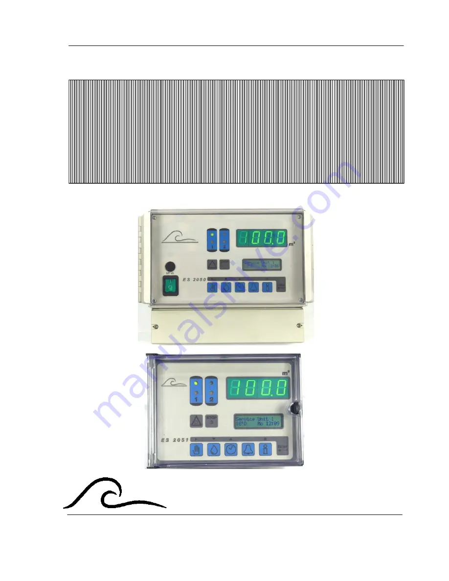
ES 2050
ES 2051
Software version 4.01
Page 1: ...Electronic Controllers for water softening units Instruction Manual ES 2050 ES 2051 Software version 4 01...
Page 2: ...d water produced 7 Inputs 8 Outputs 8 Service Telephone number 8 Maintenance 8 Software version 8 Alarms warnings 9 Programmed capacity exceeded 9 Electrical supply failure 10 Refill chemical tank 10...
Page 3: ...y hardness 25 9 Exchange capacity 26 10 Pre regeneration signalling 27 11 Number of valve switching pulses 28 12 Electrical control 28 13 Pulse timing 30 14 Regeneration times 31 15 Additional program...
Page 4: ...day when regeneration would be undesirable e g periods of high demand the control can be programmed so that regeneration cannot take place between certain times When this postponed regeneration facil...
Page 5: ...r 15 Numerical input 2 Regeneration unit1 9 Supply water hardness 16 Programming 3 Alarms 10 Next program 17 service unit 2 4 Warnings 11 Real Time 18 LED Display 5 Fuse 12 Previous program 19 Regener...
Page 6: ...e bottom right hand corner of the display This flashes when flushing has been commenced see step 15 in the basic programme LED control lamps Coloured lamps are used to give the most important status i...
Page 7: ...lume of water has been supplied When this output is active the second line of the display shows the remaining signal duration Regeneration status The first line of the LCD display indicates the actual...
Page 8: ...English hardness degrees Milligrams per litre as CaCO3 Grains per gallon 2 99 4 199 2 99 40 1990 2 99 The controller automatically recalculates the capacity between regeneration s using the new value...
Page 9: ...rmation is displayed Flush period The programmed volume between successive flush signals the volume remaining to the next flush signal and the duration of the flush signal are displayed Regeneration t...
Page 10: ...ming instructions the selected start time and the duration of the additional program are displayed if Step 0 is displayed the additional routine will operate before regeneration can commence similarly...
Page 11: ...ephone number Select the digit using the 8 key the number can then be changed by using either the 6 or t key Maintenance If the automatic maintenance required warning is programmed the pre set mainten...
Page 12: ...arge tank being filled very rapidly Possible causes when regeneration is remotely initiated by water analysis equipment signal Faulty analytical equipment Incorrect operation of analysis unit Water an...
Page 13: ...Press the UNLOCK key indicated by the symbol in order to reset the warning or alarm relay and then reset the current time Refill chemical tank NOTE This message can only appear only if there is a rege...
Page 14: ...ed it is not possible to manually reset the message relay With duplex installations operating in standby mode the stand by unit will be brought on line if there is a wait signal when a regeneration cy...
Page 15: ...ng the sensitivity of the analytical equipment IMPORTANT Regeneration is not initiated This must be done manually this prevents repeated regeneration s due to a malfunction Press the UNLOCK key indica...
Page 16: ...which regeneration will be initiated will appear with the current time in the LCD display In a duplex plant operating in standby mode the stand by unit is brought into service If the prohibited time...
Page 17: ...med that there will be sufficient chemicals present for one regeneration By pushing the key REGENERATION INITIATION indicated by the symbol it will is possible to override the warning and initiate a r...
Page 18: ...ing instructions if an attempt is made to initiate a regeneration during this interval the minimum regeneration time warning will be displayed Regeneration will not be initiated manual initiation will...
Page 19: ...eration of the standby unit Press the TIME key simultaneously with the UNLOCK key On a duplex plant regeneration of the stand by unit is initiated after 2 seconds delay Regeneration stop Press the REG...
Page 20: ...seconds delay the flush will commence If the flush is already in operation using this key combination will end the flush period Regeneration without counter reset For maintenance purposes it is possi...
Page 21: ...LCD four seconds later NOTE For steps 2 and 3 the ENTER key must be held down 2 To change the language in the LCD display hold the key down and use the 4 key to move the cursor to the symbol of the co...
Page 22: ...valve ATTENTION When using this valve the instructions vary in a number of details 2 Pre service regeneration If the treated water is used for drinking purposes then it is important to prevent bacter...
Page 23: ...ds For a simplex installation it is possible to choose whether the outlet supply valve SV remains open until regeneration starts or is closed immediately If the outlet valve remains open it is importa...
Page 24: ...ime programmed in step 3 8 not activated activated Enter the time at which the unit in service will go into regeneration Select the day s for starting regeneration of the unit in service at the time p...
Page 25: ...danger of micro organism formation within the unit due to a prolonged standby period The facility is used to override volume dependant or quality dependant initiation At each time controlled regenerat...
Page 26: ...ecause of unsaturated brine If a water softener installation is also equipped with water hardness monitoring equipment the minimum time period between regeneration s must be programmed Otherwise shoul...
Page 27: ...e is an interval of 0 5 sec between output pulses 7 Flow pulse De alkalisation If the de alkalisation software option has been selected Relay K9 is used to control the fill chemical fill valve of the...
Page 28: ...these units of water hardness is given below D F E mg l CaCO3 gpg USA mmol l D 1 1 78 1 25 17 85 1 04 0 18 F 0 56 1 0 70 10 00 0 58 0 10 E 0 80 1 43 1 14 30 0 83 0 14 mg l CaCO3 0 056 0 10 0 07 1 0 05...
Page 29: ...an be softened by each unit is automatically calculated as follows Example 1 36000mg CaCO3 x 1000 100 m3 360mg l CaCO3 or Example 2 2020 F m3 50 5m3 40 F The exchange capacity can be entered as a nume...
Page 30: ...er to be held in reserve for use the following day For example with a capacity of 180 m3 and pre contact at 80 there would be a treated water reserve capacity of 36 m3 When less than 36 m3 of treated...
Page 31: ...e control 2 Pulse switching 4 EURO control IMPORTANT When valve systems operate at 24 V current loading may be very high especially if the regeneration valve and several service valves are actuated si...
Page 32: ...tching the 5th step is activated with a voltage on connections 5 8 Pulse switching With this type of control a pulse is given across connections 5 7 as soon as the next switching step is activated Exa...
Page 33: ...8 12 4 and 3 15 respectively for the duplex column With duplex installations in exchange mode Program step 1 2 YES it is possible to flush the standby stream before entering service This is achieved b...
Page 34: ...ny value between 1 and 255 minutes can be programmed in For example for a 3 step regeneration Backwash Stage 1 10 min Injection slow rinse Stage 2 60 min Fast rinse Stage 3 15 min To adjust the step t...
Page 35: ...the output to operate for a time period of between 1 and 999 minutes Programme step 15 2 15 4 or 2 FL A timed flush signal which can be used to open a dump valve flushing the plant to drain each time...
Page 36: ...eneration cycle can also begin simultaneously The additional program can either be shorter the same or of even longer duration than the regeneration program In this case program in the phase of regene...
Page 37: ...ng in stand by mode should the stand by unit be brought on at the start of the additional programme Change over Y or at the start of the regeneration of the exhausted unit Change over N ATTENTION If t...
Page 38: ...the programming the relay will function as a collective alarm or warning relay Capacity exceeded Displays 16 1 16 4 only occur with 2 filter systems In step 16 2 the user has to decide whether the out...
Page 39: ...generation The initiation of the regeneration will be held off By pressing the Start button with the symbol the signal can be overridden for the period of the regeneration By using the fast programme...
Page 40: ...riod for the Start input NOTE If the Wait input is selected in program step 17 1 for the service cycle the delay time is not reset until a service valve is open and the input is no longer active i e n...
Page 41: ...ontact The following relay outputs are also available AD Additional program routine signal programmable during regeneration RE Regeneration regeneration taking place FL Water flow water meter pulse Th...
Page 42: ...control of positioning Valve with integral program routine external control Pulsed live output at terminal 7 14 Maintained drive supply from terminal 4 Remote control valves or pilot stagers which au...
Page 43: ...ves if required Relay outputs RE and FL may be treated similarly Inputs WM water meter WA wait RS regeneration start These inputs are activated by closed a volt free contact Input RC regeneration chem...
Page 44: ...ES 2050 51 Electrical connection details 41 ES 2050 and ES 2051...
Page 45: ...f the installation IMPORTANT The front plate of the panel is provided with a plug link to the earth connection ensure that this is not disconnected during commissioned and installation Switch the equi...
Page 46: ...e inputs Contacts loaded up to a max 9V 8mA Protection class IP 65 ES 2050 IP 42 ES 2051 Ambient temperature 0 50 C Weight approximately 2 8 kg Dimensions Type ES 2050 wall mounted W x H x D 263 x 216...
Page 47: ...pe ES2050 Manufacturer EWS Equipment for Water treatment Systems International B V Product environment This product is intended for use in residential en light industrial environments Emission standar...
Page 48: ...to the carrier e Removal or installation of the product f Any other cause which does not relate to a product defect g Cartons equipment enclosures cables or accessories uses in conjunction with the pr...
Page 49: ...ally prohibited by applicable law EWS shall not be liable for 1 Damage to other property caused by defects in the EWS product damages based upon inconvenience loss of use of the product loss of time c...