background image


Design and function 

Organising welding tasks (Mode "JOB Manager") 


099-004854-EW501 

19.02.2014


77 


5.12


Organising welding tasks (Mode "JOB Manager") 


NOTE 


After carrying out any of the actions described, the machine switches back to the 
default parameters such as current and voltage. 
To ensure that all the changes are active, the welding machine should only be switched 
off after 5 seconds have elapsed. 


The JOB Manager can be used to load, copy or save JOBs. 

A JOB is a welding task defined using the 4 main welding parameters  
•  welding process,  
•  material type,  
•  electrode diameter and  
•  seam type. 
One program sequence can be defined in each JOB. 

Up to 16 programs (P0 to P15) can be set in each program sequence. 

The user has a total of 249 JOBs available. 121 of these JOBs are pre-programmed. A further 128 JOBs 
can be freely defined. 

A distinction is made between two memory sectors: 
•  121 factory-set, pre-programmed, permanent JOBs. Permanent JOBs are not loaded but are defined 

by the welding task (each welding task is permanently assigned a JOB number). 

•  128 freely definable JOBs (JOBs 129 to 256) 

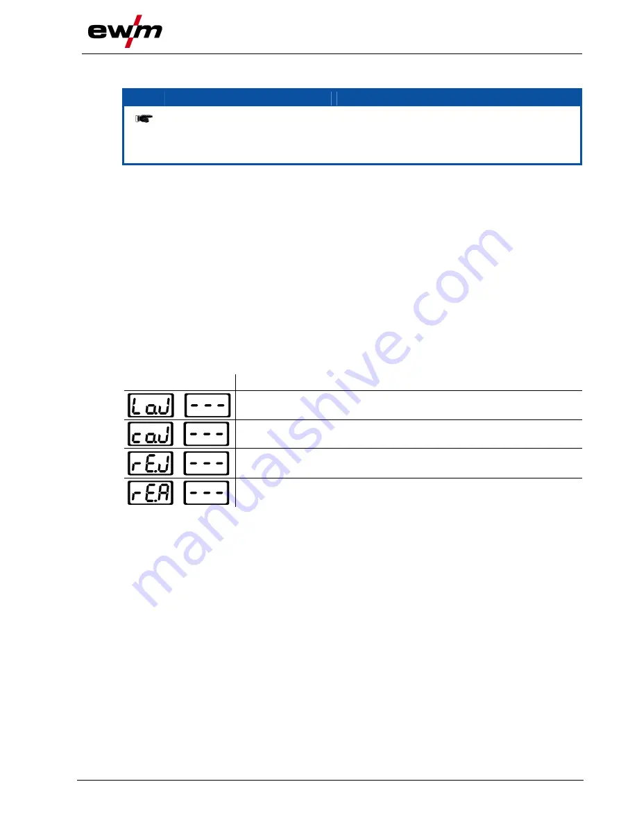
5.12.1


Explanation of symbols 

Display 

Meaning 


Load JOB 


Copy JOB 


Reset JOB 


Reset all JOBs 


Summary of Contents for Tetrix 350

Page 1: ...tructions Welding machine Tetrix 350 AC DC Synergic Plasma 099 004854 EW501 19 02 2014 Register now For your benefit Jetzt Registrieren und Profitieren www ewm group com Details for ewm warranty www e...

Page 2: ...ther form of liability regardless of type shall be accepted This exclusion of liability shall be deemed accepted by the user on commissioning the equipment The manufacturer is unable to monitor whethe...

Page 3: ...cuit diagrams 17 3 2 5 Calibration Validation 17 4 Machine description 18 4 1 Front view 18 4 2 Rear view 20 4 3 Machine control Operating elements 22 4 3 1 Function sequence 24 5 Design and function...

Page 4: ...cal cup formation 50 5 9 11 Function sequences operating modes 51 5 9 11 1 Explanation of symbols 51 5 9 11 2 Non latched mode 52 5 9 11 3 Latched mode 53 5 9 11 4 TIG spotArc 54 5 9 11 5 Spotmatic 56...

Page 5: ...5 13 4 Manual remote control RTP2 19POL 82 5 13 5 RTP3 spotArc 19POL manual remote control 82 5 13 6 Manual remote control RT AC 1 19POL 82 5 13 7 Manual remote control RT PWS 1 19POL 83 5 13 8 Foot...

Page 6: ...st for rectifying faults 101 7 2 Machine faults error messages 103 7 3 Resetting welding parameters to the factory settings 105 7 4 Display machine control software version 106 7 5 General operating p...

Page 7: ...Contents Notes on the use of these operating instructions 099 004854 EW501 19 02 2014 7...

Page 8: ...l in the page margin CAUTION Working or operating procedures which must be closely observed to prevent possible minor personal injury The safety information includes the CAUTION keyword in its heading...

Page 9: ...ess Do not press Turn Switch Switch off machine Switch on machine ENTER ENTER ENTER enter the menu NAVIGATION NAVIGATION Navigating in the menu EXIT EXIT Exit the menu 4 s Time display example wait 4s...

Page 10: ...s and burns on contact Even low voltages can cause you to get a shock and lead to accidents Do not touch any live parts in or on the machine Connection cables and leads must be free of faults Switchin...

Page 11: ...accidents if these safety instructions are not observed Non observance of these safety instructions is potentially fatal Carefully read the safety information in this manual Observe the accident prev...

Page 12: ...currents Stray welding currents can destroy protective earth conductors damage equipment and electronic devices and cause overheating of components leading to fire Make sure all welding leads are sec...

Page 13: ...he user is responsible for any interference caused by welding In order to evaluate any possible problems with electromagnetic compatibility in the surrounding area the user must consider the following...

Page 14: ...itable for transport by hand only The machine may not be lifted by crane or suspended CAUTION Risk of tipping There is a risk of the machine tipping over and injuring persons or being damaged itself d...

Page 15: ...ge the equipment Avoid high volumes of smoke vapour oil vapour and grinding dust Avoid ambient air containing salt sea air Non permissible ambient conditions Insufficient ventilation results in a redu...

Page 16: ...between the welding torch and the weld pool e g during manual welding Voltage losses as a result of a shortening of the distance between the torch and molten pool are compensated by a current rise am...

Page 17: ...d with the unit 3 2 3 Welding in environments with increased electrical hazards In compliance with IEC DIN EN 60974 VDE 0544 the machines can be used in environments with an increased electrical hazar...

Page 18: ...04854 EW501 19 02 2014 4 Machine description NOTE The maximum possible machine configuration is given in the text description If necessary the optional connection may need to be retrofitted see Access...

Page 19: ...ocket Plasma welding torch nozzle potential 9 Connection socket welding current TIG Plasma welding current connection 10 5 pole connection socket welding torch control lead 11 G1 4 shielding gas conne...

Page 20: ...Machine description Rear view 20 099 004854 EW501 19 02 2014 4 2 Rear view Figure 4 2...

Page 21: ...re reducer 5 G1 4 connecting nipple shielding gas connection Connection to the pressure reducer 6 Cooling air outlet 7 Pilot current connection socket Plasma welding torch nozzle potential 8 Mains con...

Page 22: ...and safe welding Aluminium magnesium alloys AC welding with trapezoidal current output wave form An all rounder suitable for most applications Aluminium silicon alloys AC welding with sinusoidal curre...

Page 23: ...dicators Collective interference signal light Water deficiency signal light welding torch cooling Excess temperature signal light safety sign signal light 10 Display switching button Material thicknes...

Page 24: ...00 s to 20 0 s 0 1 s increments 5 AMP Main current TIG pulse current I min to I max 1 A increments Main current MMA I min to I max 1 A increments 6 sec Pulse time slope time from AMP to AMP Pulse tim...

Page 25: ...ctory setting Optimisation of cleaning effect and fusion penetration characteristics Balance fast TIG DC pulses Setting range 1 to 99 1 increments 13 Alternating current frequency TIG AC 50 Hz to 200...

Page 26: ...e not locked connections and leads heat up and can cause burns if touched Check the welding current connections every day and lock by turning in clockwise direction if necessary Risk from electrical c...

Page 27: ...d lock accessory components into the relevant connection socket when the machine is switched off Comprehensive descriptions can be found in the operating instructions for the relevant accessory compon...

Page 28: ...etwork has to be suitable for operating devices according to protection class 1 5 5 1 Mains configuration NOTE The machine may be connected to a three phase system with four conductors and an earthed...

Page 29: ...unit Figure 5 2 Item Symbol Description 0 1 8 pole connection socket Cooling unit control lead 2 4 pole connection socket Cooling unit voltage supply 3 Cooling module Control and supply lead to the we...

Page 30: ...he connection between the welding machine and the GMU is created using the supplied gas connection lines with G 1 4 crown nuts connected on both sides The GMU can be used for plasma or TIG welding Ada...

Page 31: ...t Plasma welding torch nozzle potential 13 5 pole connection socket welding torch control lead Create the connection between the G1 4 shielding gas connecting nipple welding machine output and the G1...

Page 32: ...ter G1 8 plug in nipple 8 G1 4 plasma gas connecting nipple welding machine output Connection to the welding torch or gas metering unit GDE Insert the plug on the welding current lead into the welding...

Page 33: ...the gas manufacturer and in any relevant regulations concerning the use of compressed air Place shielding gas cylinders in the holders provided for them and secure with fixing devices Avoid heating th...

Page 34: ...ylinder bracket Secure the shielding gas cylinder using a securing chain NOTE Before connecting the pressure regulator to the gas cylinder open the cylinder valve briefly to expel any dirt Tighten the...

Page 35: ...gas connection Connection to the pressure reducer Screw the connection coupling of the plasma gas line onto the G1 4 connecting nipple plasma gas connection Screw the connection coupling of the shield...

Page 36: ...the shielding gas quantity to suit the welding task 5 7 4 3 Gas test Operating element Action Result 1 x Select gas test Gas pre flow time TIG signal light is on Shielding gas flows for approx 20 seco...

Page 37: ...ma automation 1 6 mm 5 A to 100 A DC 132 Plasma automation 1 6 mm 5 A to 150 A DC 140 Manual plasma welding 3 2 mm 5 A to 40 A DC 150 Manual plasma welding 3 2 mm 5 A to 120 A AC NOTE All JOBs can be...

Page 38: ...in addition to the Material thickness signal light the user is in program mode programs 1 15 see chap Welding programs If the JOB number signal light is on in addition to the Material thickness light...

Page 39: ...button illuminates CAUTION Oxidation of the tungsten electrode To protect the tungsten electrode against oxidation carry out the following actions before switching off the power source Switch off the...

Page 40: ...tly When using a gas cooled welding torch add a tube bridge to the coolant circuit see chapter Accessories NOTE Prepare welding torch according to the welding task in hand see operating instructions f...

Page 41: ...g gas supply shielding gas cylinder for welding machine WARNING Incorrect handling of shielding gas cylinders Incorrect handling of shielding gas cylinders can result in serious and even fatal injury...

Page 42: ...linder bracket Secure the shielding gas cylinder using a securing chain NOTE Before connecting the pressure regulator to the gas cylinder open the cylinder valve briefly to expel any dirt Tighten the...

Page 43: ...e shielding gas quantity to suit the welding task 5 8 2 3 Gas test Operating element Action Result 1 x Select gas test Gas pre flow time TIG signal light is on Shielding gas flows for approx 20 second...

Page 44: ...e used to select the welding task JOB All welding parameters specified here are the optimum settings for a variety of applications but they can also be modified individually The required welding curre...

Page 45: ...ameter setting in the functional sequence Figure 5 10 5 9 2 Conventional parameter setting in the functional sequence All welding parameters in the functional sequence can also be adjusted regardless...

Page 46: ...g factory setting off conventional parameter setting NOTE ENTER enter the menu Switch off machine at the main switch Press and hold the welding parameters button and switch the machine on again at the...

Page 47: ...Manual Select ignition optimisation Select and display material type or welding current polarity TIG Synergic Select material type welding current polarity is determined automatically TIG Manual Selec...

Page 48: ...aterial thickness after approx 4 seconds If the Program number signal light is on in addition to the Material thickness signal light the user is in program mode programs 1 15 see chap Welding programs...

Page 49: ...d tungsten electrode tip onto the workpiece and press the torch trigger liftarc current flowing regardless of the main current set b Incline the torch over the torch gas nozzle to produce a gap of app...

Page 50: ...er value less ignition power 5 9 10 Optimal and fast spherical cup formation NOTE A conically ground tungsten electrode approx 35 is generally required to form an ideal spherical cup Operating element...

Page 51: ...meters such as welding current sheet metal thickness gas pre flow time etc 5 9 11 1 Explanation of symbols Symbol Meaning Press torch trigger 1 Release torch trigger 1 I Current t Time Gas pre flows I...

Page 52: ...the main current phase the welding current drops at the slope time set tS1 to the secondary current AMP After torch trigger 2 is released the welding current rises at the slope time set tS2 back to th...

Page 53: ...times for secondary current AMP or pulse edges Step 3 Press torch trigger 1 The main current drops with the set down slope time to the end crater current Iend minimum current Step 4 Release torch trig...

Page 54: ...Yes Yes Yes Short 5 999 ms 1 ms No No No When selecting the spotArc operating mode the long interval is automatically preselected When selecting the Spotmatic operating mode the short interval is auto...

Page 55: ...ss and hold torch trigger 1 The gas pre flow time elapses HF ignition pulses jump from the electrode to the workpiece the arc ignites The welding current flows and immediately assumes the value set fo...

Page 56: ...r is used for process activation The process can be activated separately for each spot or permanently see chapter Advanced settings Separate process activation The welding process has to be reactivate...

Page 57: ...carefully against the workpiece Incline the torch over the torch gas nozzle until there is a gap of approx 2 3 mm between the electrode tip and the workpiece Shielding gas flows in the set gas pre fl...

Page 58: ...ime to the main current AMP NOTE Pressing torch trigger 1 starts the slope tS1 from main current AMP to secondary current AMP Releasing the torch trigger starts the slope tS2 from the secondary curren...

Page 59: ...in standard welding but during the main current phase there is a continual switching back and forth between the pulse and pause currents at the relevant times The pulse function can also be deactivat...

Page 60: ...s the pulse and pause times frequency up to 200 Hz and the pulse edges ts1 and ts2 are entered in seconds on the control Figure 5 23 Operating element Action Result Select TIG pulses function Signal l...

Page 61: ...Figure 5 24 Operating element Action Result Display Select kHz pulses Press the TIG pulses button until the signal light lights up in red Select balance Setting range 1 to 99 1 increments Select frequ...

Page 62: ...time tpause pulse pause time Figure 5 25 5 9 13 5 AC special Application e g for welding thick metal sheets onto thin metal sheets Operating element Action Result Select TIG AC special Press the TIG...

Page 63: ...his helps prevents the tungsten electrode sticking in the molten pool and the tungsten inclusions are reduced This is particularly useful in tacking and in spot welding Operating element Action Result...

Page 64: ...ments such as torch triggers TT rockers or potentiometers can be modified individually via torch modes Explanation of symbols for operating elements Symbol Description Press torch trigger Tap torch tr...

Page 65: ...in the individual modes can be found in the tables for the corresponding torch types The welding process can of course be switched on and off in all modes using torch trigger 1 TT 1 ENTER EXIT NAVIGAT...

Page 66: ...pping function Functions mode Operating elements Welding current On Off 1 factory set Secondary current Latched mode Standard torch with two torch triggers Diagram Operating elements Explanation of sy...

Page 67: ...lanation of symbols BRT 1 torch trigger 1 BRT 2 torch trigger 2 Functions mode Operating elements Welding current On Off 1 factory set Secondary current Secondary current tapping mode latched mode Wel...

Page 68: ...rst increment Figure 5 29 ENTER EXIT NAVIGATION l 0 Figure 5 30 Display Setting selection Exit the menu Exit Torch configuration menu Set welding torch functions Setting the first increment Setting 1...

Page 69: ...n an insulated surface Shielding gas connection During MMA welding open circuit voltage is applied at the shielding gas connection G connecting nipple Place yellow insulating cap on the G connection n...

Page 70: ...with DC polarity Connection for workpiece lead Insert cable plug of the electrode holder into either the or welding current connection socket and lock by turning to the right Insert cable plug of the...

Page 71: ...or which different polarities are stipulated by the manufacturer the welding current polarity can be switched easily on the control 5 10 3 1 Selection and adjustment Operating element Action Result Di...

Page 72: ...Press until signal light comes on Set the alternating current balance Factory setting see displays 5 10 5 Hotstart The hotstart device improves the ignition of the stick electrodes using an increased...

Page 73: ...revent the electrode sticking Operating element Action Result Displays 1 x Select arcforcing welding parameter The signal light comes on in red Set arcforcing 40 rutile electrode types 0 basic electro...

Page 74: ...0 default setting the welding current can be infinitely adjusted across the entire range In programs 1 15 15 different welding currents incl operating mode and pulse function are defined Example Progr...

Page 75: ...valent way Set welding current for the corresponding program e g 75 A in program 1 NOTE When connecting a potentiometer torch or up down torch or operating a standard torch in up down mode the program...

Page 76: ...th conventional setting Figure 5 33 5 11 5 Accessories for switching over programs The user can change retrieve and save programs using the following components Programs Component Create and change Re...

Page 77: ...using the 4 main welding parameters welding process material type electrode diameter and seam type One program sequence can be defined in each JOB Up to 16 programs P0 to P15 can be set in each progra...

Page 78: ...However it is a good idea to assign specific JOB numbers in the free memory JOB 128 to 256 for specific welding tasks Operating element Action Result Display x x Select JOB Manager mode Press until t...

Page 79: ...1 x JOB loaded machine switches back to Display mode The JOB can be customised as required Current value and JOB number displayed 5 12 4 Resetting an existing JOB to the factory setting Reset JOB Oper...

Page 80: ...x Switch from Load JOB to Reset All JOBs ON Reset all JOBs to factory settings OFF Do not reset JOBs 1 x All JOBs reset to factory settings machine switches back to Display mode Current value and JOB...

Page 81: ...rs 129 to 138 The first JOB can be set as required The following graphic gives an example with the settings for max JOBs available 5 and first available JOB 145 This gives the available JOBs 145 to 15...

Page 82: ...table 5 13 4 Manual remote control RTP2 19POL Functions TIG MMA Infinitely adjustable welding current 0 to 100 depending on the preselected main current on the welding machine Pulse spot normal Freque...

Page 83: ...bol Meaning Actuate foot operated remote control start welding process Operate foot operated remote control set welding current according to application Release foot operated remote control end weldin...

Page 84: ...erating elements functions cannot be changed Welding process button Welding current polarity button Parameter values in the function sequence can be displayed but not changed 5 15 PC interface CAUTION...

Page 85: ...her 5 16 1 Synchronisation via mains voltage 50Hz 60Hz NOTE This application relates to two types of synchronisation Synchronisation between a Tetrix series machine and a competitor machine Synchronis...

Page 86: ...synchronisation interface connector plug to the 19 pole TIG interface for mechanised welding on the rear of a welding machine from the TETRIX series master HINWEIS The machine connected to the synchr...

Page 87: ...ation for master slave operation D Input no c IGRO Current flows signal I 0 maximum load 20mA 15V 0V welding current flowing E R Input Output Not Aus Emergency stop for higher level shut down of the p...

Page 88: ...cification for main current 0 10V 0V Imin 10V Imax 5 D Input Control value specification for secondary current 0 10V 0V Imin 10V Imax 6 J U Output Reference 0V 7 K Output Power supply 15V max 75mA 8 V...

Page 89: ...ed settings 5 18 1 TIG non latched operating mode C version ENTER EXIT NAVIGATION l 0 Figure 5 38 Display Setting selection Exit the menu Exit Machine configuration Settings for machine functions and...

Page 90: ...safety information in this manual Observe the accident prevention regulations in your country Inform persons in the working area that they must observe the regulations CAUTION Test Before re commissio...

Page 91: ...can be displayed as percentages factory setting or absolute values on the machine display ENTER EXIT NAVIGATION l 0 Figure 5 40 Display Setting selection Exit the menu Exit Machine configuration Setti...

Page 92: ...TER EXIT NAVIGATION l 0 Figure 5 41 Display Setting selection Exit the menu Exit Machine configuration part two Settings for machine functions and parameter display Ramp function Remote control RTF 1...

Page 93: ...5 42 Display Setting selection Expert menu Slope time tS1 main current to secondary current Setting 0 00 s to 20 0 s factory setting 0 00 s Slope time tS2 secondary current to main current Setting 0 0...

Page 94: ...welding parameters button and switch the machine on again at the same time NAVIGATION navigating in the menu Parameters are selected by pressing the welding parameters button Set or change the parame...

Page 95: ...Design and function Menus and sub menus on the machine control 099 004854 EW501 19 02 2014 95 EXIT NAVIGATION ENTER l 0 Figure 5 43...

Page 96: ...art currents Pro welding current display as a percentage of the main current factory setting Abs absolute welding current display Non latched operation C version on on off off factory setting Setting...

Page 97: ...5 Expert menu AC mean value controller on on factory setting off off Switching option for welding current potential dc with TIG DC off Select option for TIG DC is blocked factory setting Serves to pr...

Page 98: ...t the values in the machine configuration menu CPL Complete reset of all values and settings The reset is performed when leaving the menu EXIT Software version query example 07 System bus ID 0340 Vers...

Page 99: ...es Functional test Welding current cables check that they are fitted correctly and secured Gas tubes and their switching equipment solenoid valve Gas cylinder securing elements 6 2 2 Monthly maintenan...

Page 100: ...ng to European provisions guideline 2002 96 EG of the European Parliament and the Council of January 27th 2003 used electric and electronic equipment may no longer be placed in unsorted municipal wast...

Page 101: ...ow Check coolant level and refill if necessary Eliminate kinks in conduit system hose packages Reset automatic cutout of the coolant pump by activating Air in the coolant circuit see chapter Vent cool...

Page 102: ...sary higher ignition energy Unstable arc Material inclusions in the tungsten electrode due to contact with filler material or workpiece Regrind or replace the tungsten electrode Incompatible parameter...

Page 103: ...voltage Switch machine off and on again inform the service department if the error continues Err 10 PE error Err 11 FastStop position Edge Acknowledge error signal 0 to 1 via robot interface if availa...

Page 104: ...e The excess temperature of the high frequency blocking inductor has triggered Allow equipment to cool down Adjust processing cycle times if necessary Reset error via robot interface reset error Err 3...

Page 105: ...menu Exit Service menu Modifications to the service menu may only be carried out by authorised maintenance staff Reset reset to factory settings off aus factory setting CFG Reset the values in the ma...

Page 106: ...tware version query example 07 System bus ID 0340 Version number System bus ID and version number are separated by a dot 7 5 General operating problems 7 5 1 Interface for automated welding WARNING No...

Page 107: ...circuit NOTE Coolant tank and quick connect coupling of coolant supply and return are only fitted in machines with water cooling To vent the cooling system always use the blue coolant connection whic...

Page 108: ...00 DC 350 A 325 A 260 A 350 A 290 A 230 A Load alternation 10 min 60 DC 6 min welding 4 min pause Open circuit voltage with AC and DC 100 V Mains voltage tolerances 3 x 400 V 25 to 20 Frequency 50 60...

Page 109: ...antity meters 090 008081 00000 5POLE CEE 32A M Machine plug 094 000207 00000 2M G1 4 G3 8 DIN EN 559 Gas tube 2 m 092 000525 00001 GH 2X1 4 2M Gas hose 094 000010 00001 ADAP3 G1 4 G1 4 LKS Threaded ad...

Page 110: ...ultaneous two sided welding according to the master slave principle both welding machines must be fitted with the 19 pole connection socket ON 19POL Note different retrofitting options depending on th...

Page 111: ...e St 2 5 CrNi Fe St 2 4 6 CrNi Fe St 3 2 7 CrNi Fe St 3 2 8 CrNi Fe St 1 9 CrNi Fe St 1 6 10 CrNi Fe St 2 11 CrNi Fe St 2 4 12 CrNi Fe St 3 2 13 CrNi Fe St 3 2 14 CrNi Fe St 1 15 CrNi Fe St 1 6 16 CrN...

Page 112: ...uZn 3 2 38 Cu CuZn 1 39 Cu CuZn 1 6 40 Cu CuZn 2 41 Cu CuZn 2 4 42 Cu CuZn 3 2 43 Cu CuZn 3 2 44 Cu CuZn 1 45 Cu CuZn 1 6 46 Cu CuZn 2 47 Cu CuZn 2 4 48 Cu CuZn 3 2 49 Cu CuZn 3 2 50 AlMg 1 51 AlMg 1...

Page 113: ...i 1 75 AlSi 1 6 76 AlSi 2 77 AlSi 2 4 78 AlSi 3 2 79 AlSi 3 2 80 AlSi 1 81 AlSi 1 6 82 AlSi 2 83 AlSi 2 4 84 AlSi 3 2 85 AlSi 3 2 86 AlSi 1 87 AlSi 1 6 88 AlSi 2 89 AlSi 2 4 90 AlSi 3 2 91 AlSi 3 2 92...

Page 114: ...3 2 121 Al99 3 2 122 TIG manual TIG classic 123 Classic electrode 124 Reserved 125 Reserved 126 Reserved 127 Electrode JOB 128 Reserved 129 179 Free JOBs or SCO e g plasma 180 CrNi FeSt 2 4 181 CrNi F...

Page 115: ...Appendix B Overview of EWM branches 099 004854 EW501 19 02 2014 115 11 Appendix B 11 1 Overview of EWM branches...

Reviews: