Design and function
MIG/MAG welding
26
099-005548-EW501
27.10.2017
Depending on the wire electrode diameter or type, either a steel liner or liner with the correct inner
diameter must be inserted in the torch!
Recommendation:
• Use a steel liner when welding hard, unalloyed wire electrodes (steel).
• Use a chrome nickel liner when welding hard, high-alloy wire electrodes (CrNi).
• Use a plastic or teflon liner when welding or brazing soft wire electrodes, high-alloy wire electrodes or
aluminium materials.
Preparation for connecting welding torches with a spiral guide:
• Check that the capillary tube is correctly positioned in relation to the central connector!
Preparation for connecting welding torches with a liner:
• Push forward the capillary tube on the wire feed side in the direction of the Euro torch connector and
remove it there.
• Insert the liner guide tube from the Euro torch connector side.
• Carefully insert the welding torch connector with as yet too long a liner into the Euro torch connector
and secure with a crown nut.
• Cut off the liner with a liner cutter
> see 9 chapter
just before the wire feed roller.
• Loosen the welding torch connector and remove.
• Carefully chamfer the cut off end of the liner with a liner sharpener
> see 9 chapter
and sharpen.
Some wire electrodes (e.g. self-shielding cored wire) are welded using negative polarity. In this
case, the welding current lead should be connected to the "-" welding current socket, and the
workpiece lead should be connected to the "+" welding current socket. Observe the information
from the electrode manufacturer!
Choose welding current connection socket according to the signal light for the polarity setting!
• Select JOB > see 5.3.4 chapter
• Polarity selection “+” or polarity selection “-” signal lights show the polarity setting.
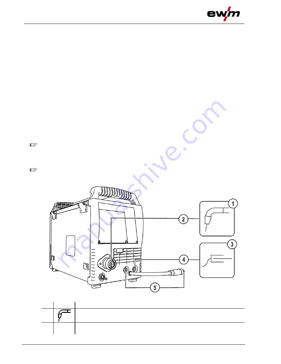
Figure 5-10
Item Symbol
Description
0
1
Welding torch
2
Welding torch connection (Euro or Dinse torch connector)
Welding current, shielding gas and torch trigger integrated


