background image


Machine description – quick overview

Pico 300 cel


099-002032-EW501 

29.04.2010


15


Item Symbol Description 

0


Carrying strap  


Transport bar 


Carrying handle 

4  

Machine control 
See Machine control – operating elements chapter 


Cooling air inlet 


Connection socket, "+" welding current 
•  TIG: Connection for workpiece lead 
•  MMA: Electrode holder or workpiece lead connection 


Connection socket, 19-pole 
Remote control connection 


Connection socket, “-” welding current 

Electrode holder or workpiece lead connection 


Machine feet 

10 


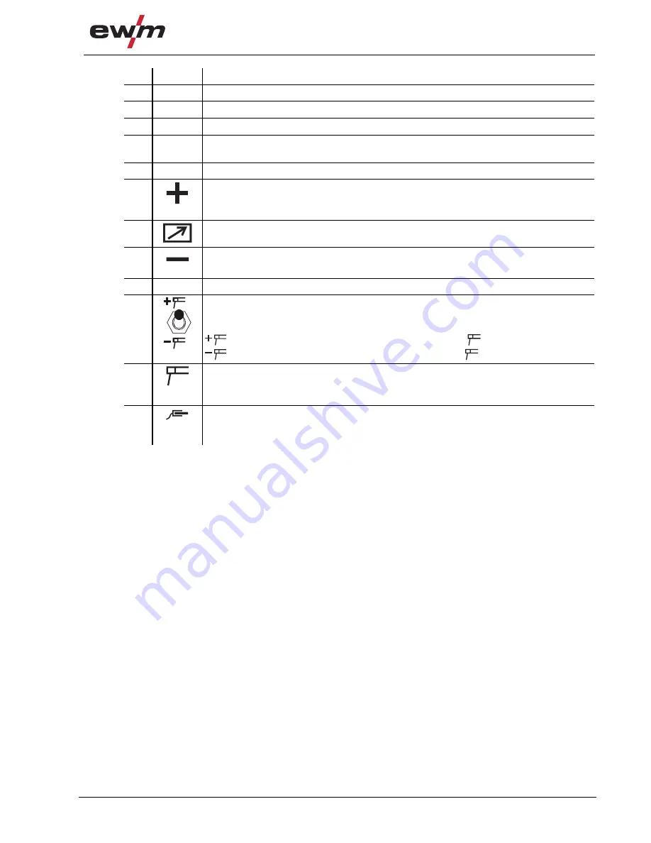
Pole reversal changeover switch 
The changeover switch is used to switch over the welding current polarity (“+” or “-” ) of 
the electrode holder and workpiece lead connection sockets. 

 = 

Welding current polarity “+” on connection socket 

 = 

Welding current polarity “-” on connection socket 

11 


Connection socket, electrode holder 

The welding current polarity (“+” or “-”) are based on the setting of the “Welding current 
polarity changeover switch”. 

12 


Connection socket, workpiece lead 
The welding current polarity (“+” or “-”) are based on the setting of the “Welding current 
polarity changeover switch". 

Summary of Contents for Pico 300 cel SVRD

Page 1: ...Operating instructions Welding machines for MMA welding GB Pico 300 cel Pico 300 cel VRD Pico 300 cel SVRD Pico 300 cel pws Pico 300 cel pws VRD Pico 300 cel pws SVRD 099 002032 EW501 29 04 2010...

Page 2: ...ther form of liability regardless of type shall be accepted This exclusion of liability shall be deemed accepted by the user on commissioning the equipment The manufacturer is unable to monitor whethe...

Page 3: ...300 cel 14 4 1 1 Front view 14 4 1 2 Rear view 16 4 2 Machine control Operating elements 18 5 Design and function 20 5 1 General 20 5 2 Machine cooling 20 5 3 Workpiece lead general 20 5 4 Transport...

Page 4: ...ork intervals 38 6 2 1 Daily maintenance tasks 38 6 2 2 Monthly maintenance tasks 38 6 2 3 Annual test inspection and testing during operation 38 6 3 Repair Work 39 6 4 Disposing of equipment 39 6 4 1...

Page 5: ...ARNING keyword in the heading with a general warning symbol The hazard is also highlighted using a symbol in the page margin CAUTION Working or operating procedures which must be closely observed to p...

Page 6: ...t points e g Insert the welding current lead socket into the relevant socket and lock Symbol Description Press Do not press Turn Switch 0 1 Switch off machine 0 1 Switch on machine ENTER enter the men...

Page 7: ...ich can result in potentially fatal electric shocks and burns on contact Even low voltages can cause you to get a shock and lead to accidents Do not touch any live parts in or on the machine Connectio...

Page 8: ...ny easily flammable objects such as matches or lighters Keep appropriate fire extinguishing equipment to hand in the working area Thoroughly remove any residue of flammable substances from the workpie...

Page 9: ...regular intervals that users are working in a safety conscious way Regular checks of the machine according to IEC 60974 4 Damage due to the use of non genuine parts The manufacturer s warranty becomes...

Page 10: ...tipping over and injuring persons or being damaged itself during movement and set up Tilt resistance is guaranteed up to an angle of 10 according to IEC 60974 1 3 10 Set up and transport the machine...

Page 11: ...s of dust acid corrosive gases or substances may damage the equipment Avoid high volumes of smoke vapour oil vapour and grinding dust Avoid ambient air containing salt sea air Non permissible ambient...

Page 12: ...d with special Arcforce characteristics These device types facilitate welding with cellulose electrode types which is safe for vertical down welding especially in the lower output range 3 2 2 Pole rev...

Page 13: ...ted conversion work not specifically authorised by the manufacturer The original copy of the declaration of conformity is enclosed with the unit 3 3 3 Welding in environments with increased electrical...

Page 14: ...Machine description quick overview Pico 300 cel 14 099 002032 EW501 29 04 2010 4 Machine description quick overview 4 1 Pico 300 cel 4 1 1 Front view Figure 4 1...

Page 15: ...t welding current Electrode holder or workpiece lead connection 9 Machine feet 10 Pole reversal changeover switch The changeover switch is used to switch over the welding current polarity or of the el...

Page 16: ...Machine description quick overview Pico 300 cel 16 099 002032 EW501 29 04 2010 4 1 2 Rear view Figure 4 2...

Page 17: ...Pico 300 cel 099 002032 EW501 29 04 2010 17 Item Symbol Description 0 1 Main switch machine on off 2 Mains connection cable 3 Cooling air outlet 4 F4 Fuse Solenoid switch pole reversal fuse 5 F5 Fuse...

Page 18: ...Machine description quick overview Machine control Operating elements 18 099 002032 EW501 29 04 2010 4 2 Machine control Operating elements Figure 4 3...

Page 19: ...ing current and voltage welding parameters error code 4 Switch display button AMP Welding current display VOLT Welding voltage display 5 Welding process button MMA welding TIG welding 6 Arcforce butto...

Page 20: ...Using protective dust caps Protective dust caps protect the connection sockets and therefore the machine against dirt and damage The protective dust cap must be fitted if there is no accessory compone...

Page 21: ...on a suitable stable and level base The operator must ensure that the ground is non slip and level and provide sufficient lighting for the place of work Safe operation of the machine must be guarantee...

Page 22: ...ins plug socket and lead must be checked regularly by an electrician 5 5 1 Mains configuration NOTE The machine may be connected to TN TT or IT networks with a protective conductor as available L1 L3...

Page 23: ...he electrode manufacturer given on the electrode packaging 5 6 1 Connecting the electrode holder and workpiece lead 5 6 1 1 Pico 300 cel Figure 5 3 Item Symbol Description 0 1 Electrode holder 2 Conne...

Page 24: ...pws NOTE The pole reversal changeover switch allows the welding current polarity to be changed without unplugging the electrode holder or workpiece leads Changeover can also be carried out using a su...

Page 25: ...on the setting of the Welding current polarity changeover switch 5 Pole reversal changeover switch The changeover switch is used to switch over the welding current polarity or of the electrode holder...

Page 26: ...at low current strengths with a short arc in particular NOTE The selectable electrode characteristics on the machine control are guideline values Every characteristic can also be optimised for the rel...

Page 27: ...ent until the hotstart time in seconds has elapsed factory setting 1 second The hotstart current then reduces to the main current set Symbol Meaning AMP Main current AMP Hotstart current sec Hotstart...

Page 28: ...adjusted or optimised for the welding task 5 6 5 1 Arcforce correction welding characteristics NOTE To change the advanced setting parameters hold down the Welding parameters button for 2 seconds aft...

Page 29: ...inders in the holders provided for them and secure with fixing devices Avoid heating the shielding gas cylinder CAUTION Faults in the shielding gas supply An unhindered shielding gas supply from the s...

Page 30: ...ght Screw the shielding gas connection of the welding torch to the pressure reducer on the shielding gas cylinder Slowly open the gas cylinder valve Open the rotating valve on the welding torch Before...

Page 31: ...pressure reducer 4 Welding torch 5 Connection socket welding current Welding current lead connection for TIG welding torch Insert the welding current plug on the welding torch into the welding current...

Page 32: ...current polarity Figure 5 11 Item Symbol Description 0 1 Output side of the pressure reducer 2 Welding torch 3 Connection socket TIG welding torch 4 Workpiece 5 Connection socket workpiece lead Inser...

Page 33: ...workpiece a Carefully place the torch gas nozzle and tungsten electrode tip onto the workpiece liftarc current flowing regardless of the main current set b Incline the torch towards the torch gas nozz...

Page 34: ...the greatest possible breadth of applications the following parameters can be adjusted or optimised for the welding task 5 8 1 Arc length restriction USP Figure 5 13 Display Setting selection Arc len...

Page 35: ...as a setpoint value parameter rcd off After switching over to the actual value display parameter rcd on the following is displayed The setpoint value is displayed in open circuit mode when no welding...

Page 36: ...particular such as ship construction pipe construction mining VRD reduces the open circuit voltage to 12 V within 0 2 s and thus fulfils the Australian standard AS 1674 2 2003 SVRD reduces the open ci...

Page 37: ...e ambient air The filter reduces the duty cycle of the welding machine via the reduced flow of cooling air The filter must be disassembled and cleaned regularly depending on the level of dirt blow out...

Page 38: ...d secured Gas tubes and their switching equipment solenoid valve Operating message safety and adjustment devices Functional test Other general condition 6 2 2 Monthly maintenance tasks Casing damage f...

Page 39: ...provisions guideline 2002 96 EG of the European Parliament and the Council of January 27th 2003 used electric and electronic equipment may no longer be placed in unsorted municipal waste It must be co...

Page 40: ...cause Remedy E 1 Electronics error Switch the machine off and back on again If the error persists inform the service dept E 2 Temperature error Allow machine to cool down E 3 Electronics error See E 1...

Page 41: ...ttings NOTE All customised welding parameters that are stored will be replaced by the factory settings 0 1 0 1 AMP VOLT Figure 7 1 Display Setting selection Calibration The machine will be calibrated...

Page 42: ...ion 10 min 60 DC 6 min welding 4 min pause Open circuit voltage 99 V Open circuit voltage VRD 12 V Open circuit voltage SVRD 12 V Mains voltage tolerances 3 x 400 V 20 to 25 Frequency 50 60 Hz Mains f...

Page 43: ...ction cable 092 001470 00005 RA10 19POL 10M Remote control e g connection cable 092 001470 00010 RA20 19POL 20M Remote control e g connection cable 092 001470 00020 RTF1 19POLE 5M Foot operated remote...

Page 44: ...group com EWM HIGHTECWELDING GmbH Dr G nter Henle Stra e 8 56271 M ndersbach Deutschland Tel 49 2680 181 0 Fax 244 www ewm group com info ewm group com EWM SCHWEISSTECHNIK HANDELS GMBH In der Florinsk...

Reviews: